
The finished StarField Shader Graph on a Teleport booth.
Unity Shader Graph StarField Tutorial
Generate a single star,
Repeat the star in a grid layer,
Use grid cell IDs to give each star individual properties,
Duplicate the grid layers several times,
Animate the layers to suggest flying trough space.
0. Introduction


In this tutorial we will create an awesome looking star field shader using Unity’s node-based shader creation tool Shader Graph.
Though ShaderGraph is not the only way to create this shader, there is a lot that we can learn from re-creating/translating the original Starfield shader code that was created by Martijn Steinrucken from The Art of Code YouTube channel.
By doing this tutorial you will learn:
- How to generate a star using nothing but nodes.
- How to repeat the same star in a grid using the fraction node.
- Hot to give each grid cell’s star individual properties like size, position and colour by generating an ID value for each grid cell.
- How to add the contribution of all the neighbouring grid cells stars so the stars wont have their edges cut off.
- How to layer multiple grids on top of each other with different scaling so it looks like there is depth in between.
- How to animate the star layers coming towards us so it looks like we’re flying trough space by increasing scale over time.
- How to create sub-graphs…lots of ’em!
This tutorial is aimed at ShaderGraph beginners and explains everything step by step but if you’re completely new to ShaderGraph then I recommend having a look at the documentation pages first: https://docs.unity3d.com/Packages/com.unity.shadergraph@6.9/manual/Getting-Started.html
Before you start, know that this ShaderGraph, consisting of one normal graph and four sub-graphs, can also be created by using a custom function node with an .hlsl include file containing the StarField method in normal code, (see step 7.0 if you want to go at it that way) but I suspect that you are here for a learning experience and to ‘mess’ around with ShaderGraph nodes. You can definitely apply everything that you learn from following this tutorial to many other shader graphs that need a semi-random repeating pattern!
This tutorial was written using Unity 2019.4.3f1 LTS using the URP (Universal Render Pipeline).
Credits go out to The Art of Code for creating the original Starfield shader. Definitely checkout this YouTube channel for the original code tutorial and for his other cool shader tutorials!
1.0 The ShaderGraph and Sub-Graphs Structure
The complete ShaderGraph Starfield will consist out of one primary/main ShaderGraph that we’re going to call StarField.
Inside of StarField we will use a sub-graph called StarGridLayerAnimation.
Inside StarGridLayerAnimation we will use a sub-graph called StarGridLayer.
Inside StargridLayer will use a sub-graph named StarGrid.
Finally inside StarGrid will use a sub-graph called Star.
The dependency tree for the ShaderGraph and sub-graphs:
Starfield
↓
StarGridLayerAnimation
↓
StarGridLayer
↓
StarGrid
↓
Star
We will start by creating the main StarField ShaderGraph with the nodes for creating a single star first. Then we will pack those nodes into a nice Star sub-graph and then we will do the same with the other three sub-graphs, working our way up. We could create the sub-graphs all beforehand but that is not the way this ShaderGraph was created or how you would normally create it, so that would be less of a learning experience.
Anyway,.. let’s get started!…
If you want to see the shader in the Scene View during creation you can add a quad or any other model to the scene and apply a material to it that uses the shader graph shader that we’ll create in step 2:

2.0 Generating a single star

Right-click in the Project View and click Create > Shader > Unlit Graph and name it ‘StarField‘:

Double-click on the StarField graph to open it and then right-click in the empty graph and create a new UV node. Simply type ‘UV’ after clicking on Create node to find it and press Enter to add it to the graph.
Also Create a Tiling and Offset node with an offset of -0.5 and connect it to the UV and the Unlit master node. Offsetting the UV coordinates by -0.5 will place the origin at the center instead of at the bottom left corner:

The Preview node in the graph is optional and only for you to see better what is going on. You can also right-click inside of the Main Preview window to display the shader on a quad instead of on a sphere:

Add a Length node and connect it to the Tiling and Offset node to create a black to white fall-off, going from the center out towards the edges. The Length node returns the length of a vector, so how far away it is from the origin, which is in the center:

Add a Divide node to divide the length of the UV vector by a small number. This creates a soft white dot in the center:

Instead of using a hard coded value for the division, open up the blackboard if it isn’t open yet and create a new Vector1 type property named Star Size with a default value of 0.5 and with the Exposed boolean checked true.
Drag the Star Size property from the blackboard onto the graph and connect it to the Divide node to replace the hardcoded value:

By using an exposed property we can set the value from the Unity Inspector outside of the shader when we have a material that uses the shader selected or we could set it from within a C# script. (We also need the property exposed to be able to use it from another graph when we’ve turned the star function into a sub-graph):

2.1 Star flare rays
To create rays for the star we can start off by multiplying the x with the y component of the UV coordinates. This will give us a black to white gradient that is the same in the x and y directions..
Add another UV and Tiling and Offset node with a -0.5 offset (or use the ones from the star).
Also add a Split and a Multiply node.
Take the R channel (which is synonym for the x component of the UV) and multiply it by G (synonym for y).
Connect the output from the Multiply node directly to the Unlit node for now, so we can see the rays without the star:

The ‘RGBA’ output names of the Split node may be confusing if you’re not familiar with writing shader code. The reason why the Split node’s outputs are named RGBA and not xyzw is because behind the scenes the same float4 data type is used to store both colour and vector information in the form of floats.
The reason why we are left with black squares in the top left and bottom right corners is because we’re multiplying a negative with a positive number, which leads to a negative outcome, 1 multiplied by -1 is -1 so the color shows as black.
In the top right and bottom left corner we’re multiplying 1 by 1 and -1 by -1 from which the outcome is both 1, so the color shows as white.
In order to get rid of the black squares, add an Absolute node to make the negative UV coordinates the same as the positive UV coordinates, basically to get rid of the sign of a number (https://en.wikipedia.org/wiki/Absolute_value):

Now that the corners are the same you can start to see the shape of the flare, it is still black but we’ll fix that later, first let’s make the flare smaller.
Add a Multiply node and multiply the absolute coordinates by a value of 1000. In this case multiplying by a large number will decrease the size of the flare:

To flip black and white add a One Minus node that does exactly what it says, it outputs one minus the input:

Add a Maximum node that picks the largest value of the input value and 0 to make sure that the flare value cannot go below zero:

Add a Multiply node and a new exposed property named ‘Star Flare‘ with a default value of 1.
Multiply the entire flare by the Star Flare property. This will allow us to disable the flare if we set it to 0 so we can have some stars with flares but not all of them later on:

Add a Multiply node again and multiply the flare value by a new type Vector1 property called ‘Star Flare Brightness‘ so we can control the brightness separately:

And finally add one more Multiply node and multiply the Offset by a new type Vector1 property called ‘Star Flare Scale‘, so we can control the scale of the flare from the material/Inspector as well:

To get some more rays, duplicate the entire star flare function and add it to the first flare function with an Add node at the end. Then add a Rotate node after the UV node with a rotation of 45 degrees (or a quarter Pi radians) :

2.2 Star Fade-out
Because we’re going to tile the star in a grid in step 3, we have to make sure that the glow and the rays stay inside the edges of the tiles. Right now the star fades out very slowly from the center all the way to infinity but we can control the fade by ‘smoothstepping’ over the length of UV..
Add UV, Tiling and Offset, Length, Smoothstep and Multiply nodes.
Smoothstep from 0.5 to 0 over the length of UV and then multiply the star and rays by the output to make it fit the box perfectly. You can also add the star back in:

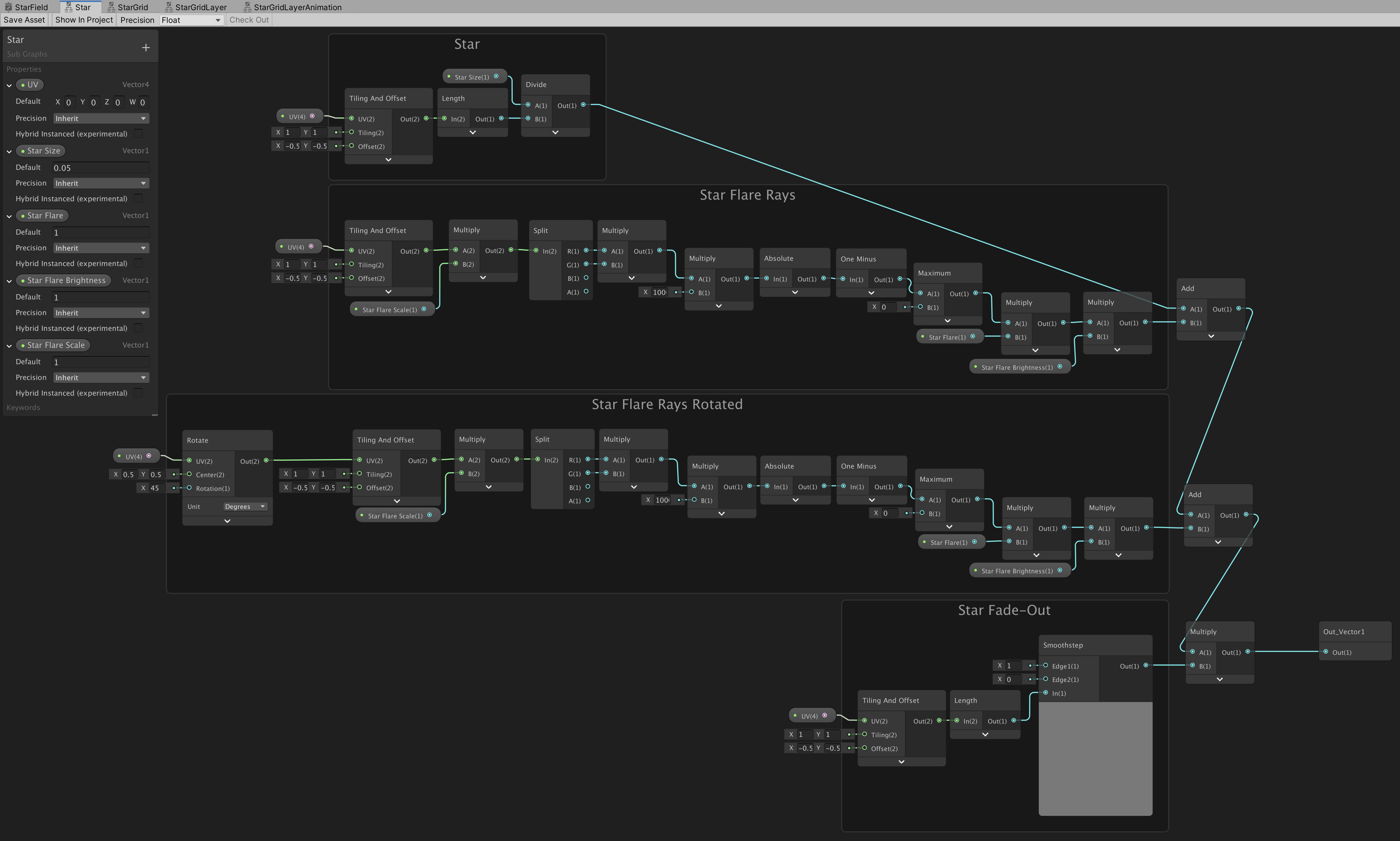
2.3 Star Sub-Graph
In step 3 we will create the star grid but it is smart to keep our star logic separate from our star grid method so we can keep the main graph organised and small. Also so that we can re-use the grid logic more easily when maybe later we want to create a grid of some other shape then a star or if we want to use only the star shape for something else.
So before we start creating the grid we’re going to embed our star logic into a sub-graph first and use that inside of the grid logic that we’re going to create in the StarField main graph..
To create a sub-graph out of the nodes that we already have, first connect the Star, Star Rays and Star Fade-Out functions/groups to the same UV node. Also connect the Star Flare, Star Flare Scale and Star Flare Brightness properties from both Star Flare Rays functions to the same nodes. If you don’t do this it’s not really a problem but Unity will create unnecessary extra properties in the sub-graph upon creation that would have to be removed:

Select all nodes except for the Unlit master and the UV node and right-click to ‘Convert to sub-graph‘. Name the new sub-graph ‘Star‘:

Double-click on the newly created Star node to open the Star sub-graph. As you can see Unity has replaced all of the properties from the main StarField graph’s blackboard correctly to the Star sub-graph except for the name of the UV property, so rename the property named ‘Vector4‘ to ‘UV‘ on the Star blackboard.
You can also put the other property nodes back into their original positions:

Now save the Star sub-graph and return to the main StarField graph. Re-drag the star properties back onto the graph and connect them to the Star node’s inputs:

3.0 Star Grid

To generate a grid of repeating stars we first take the UV coordinates and multiply/tile it with a larger number than one and then we take the fractional component of the coordinates..
If you increase the tiling of the UV for instance by four then the UV coordinates will go from 0 to 4 instead of going from 0 to 1.
By taking only the fractional component of those coordinates (the numbers after the dot) we get a UV that goes from 0 to 1 four times instead of going from 0 to 4:
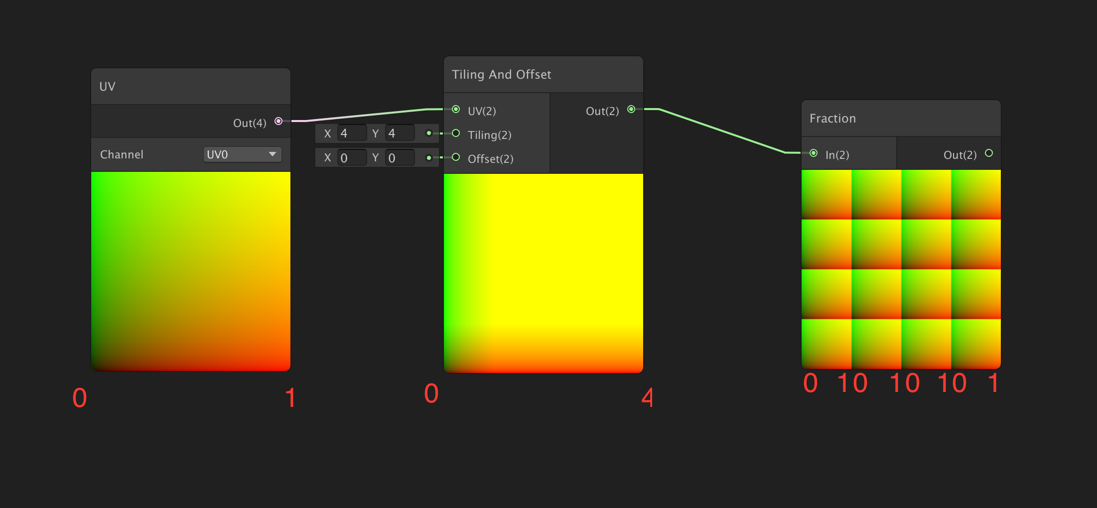
In other words, the fraction of 1.5 is the same as the fraction of 2.5 so both are 0.5 because Fraction gets rid of the integer part of a number. (If you add the fraction of a value to the floor of the same value then you just get the original value back.)
Add a new Vector1 property to the StarField’s blackboard called ‘Grid Tiling‘ with a default value of 4.
Add a Tiling and Offset and a Fraction node and plug the fraction of the tiled UV into the Star’s UV input to generate a repeating grid of stars:

3.1 Grid Cell ID
If we want to give the stars in each grid cell unique properties, like variations in size and colour, we need some kind of value that is different for each cell. To get a unique (two-dimensional) ID for each grid cell we can use a Floor node. What floor does is sort of the opposite of what Fraction does. Instead of getting rid of the integer part of a number floor gets rid of the fractional part of a number, So 1.5 floored will be 1 and 2.5 floored will be 2.
By looking at tiled and then floored UV coordinates we can get the exact column and row indexes of the grid cell that those coordinates are in. For instance if the floored UV coordinates (1.5,1.5) will be (1,1) meaning that the point is in column 1 of row 1…
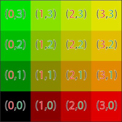
Add a Floor node and connect its input to the Tiling and Offset’s output to generate the Grid Cell IDs:

If you want to get a better visualisation for the grid cell ID’s you can divide the output of the Floor node by the value of Grid Tiling. The reason why the preview of the Floor node doesn’t show the ID’s properly without dividing is because colours don’t go higher than 1 in the previews:

3.2 Debug Outlines (Optional)
Because in the next step we are going to offset the stars inside of their cells it will get a little bit hard to see what is going on and where the ‘cell walls’ are. So before we move on we can create a Debug Outlines function to show the cell borders with red outlines. This method is optional but recommended so we and any end-user of the shader can more easily see what this shader actually does by flipping the exposed Debug boolean that this function introduces. For now checkmark the default value for Debug to true so we can see the red outlines in the graph’s preview:

3.3 Random Star Positions
If we would want the star positions to increase or decrease in size evenly across the grid then we could use the generated ID’s directly but we want the stars to get random offsets so we have to use those ID’s to generate some random numbers with. Luckily there already is a Random Range node that we can use for that. The Random Range node takes in an (x, y) seed/position as an input and spits out a single random float value based on the position that we put in..
Add a Random Range and a Subtract node.
Connect the Floor node’s output to the Random Range seed input and then subtract it from the Grid UV before connecting it to the Star:

We have some random offsets now but because we’re using the same value for the x and y offset it is always diagonal and because we’re offsetting the stars too much some of them have completely disappeared from view…
Add another Subtract node and subtract 0.5 from the random value to keep the stars inside of the cells:

To get a different random y offset we could use another Random Range node and add an offset to the seed position to get a different random number thats still based on the ID. An even shorter way is to just multiply the random value that we already have by a large number and then take the fraction of that value..
Add a Multiply, Fract and Vector2 node.
Multiply the random value by a larger number, for instance 34.5 and use the fractional component of that for the y value of the Vector2 node. Use the original random value for the x offset:

Because we’ve now changed the input type for the Subtract node from Vector1 to Vector2 we have to make sure to also subtract 0.5 from the y-axis:

3.4 Adding Neighbour Cell’s Stars
As you can see we’ve stumbled upon another problem here. Because we’ve offset the stars inside their boxes parts of the stars are now cutoff. We can fix this by adding the contributions of each surrounding neighbour cell’s star to each of the cells.
So for the cell with ID (1,1) we also add the stars from cells (0,0), (1,0), (2,0), (0,1), (1,1), (2,1), (0,2), (1,2), (2,2):
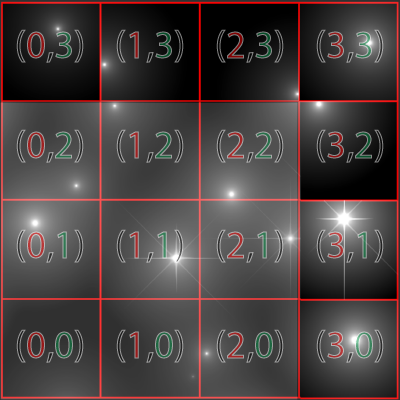
Each cell has 8 closest neighbours so we will end up with adding up a total of 9 stars for every grid cell. The original star plus the 8 neighbours. In regular shader code we could do this easily by using two nested x and y for-loops but unfortunately there is no ‘for-loop-node’ or ‘for-loop-group’ functionality that we can use in ShaderGraph at this time. We will just need to hard code our for-loop ourselves.
We could do this by copy/pasting the entire node setup for the grid eight times but it is more efficient to create another sub-graph first..
3.5 StarGrid Sub-Graph
Select the entire node setup except for the UV and the Unlit Master nodes and the Debug Outlines group.
Right-click to create a new sub-graph and call it ‘StarGrid‘.
Re-drag the properties back in the graph and connect them with the new StarGrid node’s inputs, then duplicate StarGrid and the properties 8 times and Add them all up:

Because we’re now adding 9 StarGrids based on the same UV coordinates all the stars will look much brighter so instead of using the current UV coordinates for all the grids we need to offset the UV coordinates to the coordinates of the 8 local neighbouring cells:

We can do this by adding a Offset property to the StarGrid sub-graph first..
Open up the StarGrid sub-graph and create a new type Vector2 property named ‘Grid Cell Offset‘.
(Also rename the ‘Vector4‘ property to ‘UV‘ on the blackboard again)
Add Subtract and Add nodes.
Subtract the offset grom the Grid UV before it goes into the star and Add the offset to the Grid Cell ID before it goes into the Random Range:

Because the StarGrid sub-graph is dependant on the UV input from the main graph the node previews do not work. If you want to see what is going on inside the sub-graph you can temporarily use a UV node instead of the UV property.
Just make sure to change it back when you’re done and to give all the properties on the sub-graph’s blackboard the right default values or all the previews will still remain black!:

Another option that seems to work (but I haven’t tested it fully) is to check if the UV property is equal to zero. If it is then we use the UV node and otherwise we use the UV property. This way you can see the previews in the sub-graph without breaking the main-graph:

Return to the main StarField graph and assign the right offset values to the StarGrid nodes. From top to bottom in the graph the 9 Grid Cell Offsets are,
(-1,-1) (0,-1) (1,-1) (-1,0) (0,0) (1,0) (-1,1) (0,1) (1,1):

This neatly fixed the problem with the cutoff so now we really can have repeated stars with individual random offsets!
Because we’re now adding the neighbour grid cells we can also fade-out the stars over twice the distance so if you want the stars to have larger and smoother fade-out then you can change the Smoothstep node to go from 1 to 0 in the Star sub-graph:

3.6 Random Star Sizes
Right now each star still has the same size but we can use a random value again and multiply the star by that value to get different sizes. We could use the same random value that we already have but then the size would be directly related to the offset so we can just create another random value the same way we did with the y offset value, by multiplying by an even larger number and getting the fraction of that value again..
Open the StarGrid sub-graph and add two Multiply and one Fract nodes.
Get the fraction of the random value multiplied by a number larger than the one used for the star y-offset, for instance 345.6 and then multiply the star by that value:

We can choose to only use the flares on the largest stars by adding a Smoothstep node to smoothstep from 0.9 to 1 over the the Random size to control the Star Flare input with:

(We won’t need the Star Flare property on the StarGrid sub-graph and on the main-graph’s blackboards anymore so you can remove them.)
3.7 Random Star Colours
We can use the same approach as with the random size and position to get a new random value for the star colours. For the colours we can keep it simple and artistic and just use a gradient. I’ve chosen a gradient that goes from blue, to white, to yellow, to red to represent the colours that we see the stars in, just to have some logic to it, (https://en.wikipedia.org/wiki/Stellar_classification) but feel free to choose your own colours just based on what looks good:

To increase the chance of a star being red we can use a Square root node before sampling the gradient but this is optional, we could also setup the gradient differently to increase the odds in favour of red.
Add a new Gradient type property named ‘Star Colours‘ to the blackboard and add a Multiply, Fract, Square root and a Gradient Sample node.
From right to left,..bear with me.., sample the Star Colours gradient with the square root, of the fraction, of the random value, multiplied by a larger number than the one used for the star position, for instance 3456.7:

Make sure to change the Out node’s type from Vector1 to Vector4 so the sub-graph can return all four RGBA colour channels instead of just one channel for black and white:

3.8 Twinkling Stars
Finally to give our stars some random twinkling we can get ourselves a new random value and use it to make the stars brightness go up and down periodically by the sinus of the time.
Add Time, Multiply, Sine and Remap nodes.
Remap the sine of the time from -1 <> 1 to 0.1 <> 1.
Multiply time by the speed that you want the stars to twinkle at. I’ve chosen to hardcode it at 3 but you can also create an exposed property for the twinkle speed and multiply it by that value if you want..:

Now the brightness from all the stars will up and down at the same time but we can just add a random value to the time to make the stars twinkle ‘ahead of schedule’ randomly.
Because the period of a sine wave is two Pi we multiply the random value that goes from 0 to 1 by two Pi (6.2831)…

Add Multiply and Add nodes and add the random value multiplied by at least 6.2831 to the time:

Save the StarGrid sub-graph and return to the main StarField graph…
3.9 StarGridLayer Sub-Graph
In the next steps we are going to add multiple star grid ‘layers’ together and animate the scaling so it will look like we’re flying trough space. In normal shader code we would just add up all the layers inside of a for-loop but we cannot do this in ShaderGraph so we’ll create another sub-graph that we can re-use first…
Select all of the nodes in the StarField graph except for the UV and Unlit master node.
Right-click to ‘Convert to Sub-Graph‘ and call the sub-graph ‘StarGridLayer‘:

Reconnect all of the properties to the StarGridLayer node:

4.0 Star Grid Layer Animation

To make it look like the stars are moving towards us we can scale the UV of the layers slowly over time making the stars look larger and when they reached a certain scale snap them back to the to the small scale again. Then if we do this with multiple layers that all start with a slightly different scale then it will look like we’re flying trough a starfield. Kind of like in the example below but instead of animating the movement of the layers we animate the scale:

We will start off by animating the movement of a single layer first and then we’ll turn the nodes into yet another sub-graph so it will be easier to add the multiple animated layers on top of each other.
To scale the layers out from the center instead of out from the corner we have to offset the UV by -0.5 first…
Add a Tiling and Offset node and offset the UV by -0.5..:

To scale smoothly from one value to another in percentages we can use a Lerp node. A Lerp node ‘linear interpolates’ from a to b over t (time).
When t is 0 Lerp returns the value of a, when t is one Lerp returns the value of b and when t = 0.5 Lerp returns the value in between a and b.. So you can think of t as percentages going from 0.0 to 1.0…
Add a Lerp node that lerps from 20 to 0.5 and multiply the UV by the Lerped value:

To Lerp the layer scale repeatedly from zero to one we can use the fraction of time and we can multiply the time by the speed that we want it to animate at…
Create a new exposed type Vector1 property named ‘Speed‘ with a default value of 0.1 and add Time, Fract and Multiply nodes.
Get the fraction of the time multiplied by Speed and connect it to the T input of the Lerp node:

4.1 StarGridLayerAnimation Sub-Graph
Select the entire graph except for the UV and Unlit master nodes and right-click to ‘Convert to Sub-graph‘. Name the new sub-graph ‘StarGridLayerAnimation‘ and reconnect all the inputs:

4.2 Layer Depth Offset
By duplicating the animated layer multiple times and by having each layer start the animation on a different time we can suggest that we’re moving trough space. So before we start copying the layers we have to add a depth offset property and add it to the time..
Open the StarGridLayerAnimation sub-graph and add an exposed type Vector1 property named ‘Layer Depth Offset‘ to the blackboard.
Add the depth offset to the time before getting the fraction:

Save StarGridLayerAnimation sub-graph and return to the main graph.
In the main graph add another 5 StarGridLayerAnimation nodes and add them all up.
From top to bottom give them the following Layer Depth Offsets: 0.0, 0.2, 0.4, 0.6, 0.8, 1.0

4.3 Layer UV Offset
Right now all the layers look the same but we can easily fix it by adding different UV offsets for each layer and we can use the Layer Depth Offset property to do this…
Open the StarGridLayerAnimation Sub-Graph and add Multiply and Add nodes.
Multiply Layer Depth Offset by a large number like 456.7 and add it to the UV:

4.4 Layer Fading In/Out
Great, the flying animation looks good now but the layers still pop in and out instantly. We can make them fade-in by simply multiplying the layer by the depth so if the layer is in the back at 0 it will be invisible and fully visible in the front at 1…
Add a Multiply node and multiply the layer by the Depth:

Now the layer slowly fades in but it still pops out instantly when depth reaches 1. To make the layers also fade-out slowly we can just use depth to sample a black to white to black gradient and multiply the layer by it…
Add a Sample Gradient node with a black/white/black gradient, i’ve chosen to put the white gradient key at 90% to make the layer slowly fade-in and quickly fade-out:

Sample the gradient at the depth and multiply the layer by it:

4.5 Layer Rotation
For the final step of this tutorial we will make the star layers rotate so that it looks like the camera is rotating. For this we can simply use a Rotate node and rotate the UV by the time…
Create a new exposed type Vector1 property called ‘Rotate Speed‘ with a default value of 0.1.
Add a Rotate node with the center at 0.0 and add Time and Multiply nodes.
Rotate the UV by the time multiplied by Rotate Speed:

Save the StarFieldLayerAnimation sub-graph and return to the main StarField graph to see your now complete shader in action:

5.0 Finally
Great job making it all the way to the end you.. you should be proud of yourself and give yourself a well earned pat on the back! Also,.. play around a little bit with this shader,.. see what you can improve or add.
I really hope that you enjoyed this tutorial. If you did and if you want more then have a look at my previous tutorials about making a complete skybox ShaderGraph and day/night cycle C# script over here:


Finally,..What would you like to learn next in a future tutorial? Or what did you miss in this one? Feel free to add any suggestions that you might have in the comments!


BUY ME A COFFEE
Donate $5 to buy me a coffee so I have the fuel I need to keep producing great tutorials!
$5.00
Hey fellow Shader Graph enthusiast!
Looking for a highly versatile and easy to modify system for rendering professional Screen-Space Edge-Detection based selection Silhouette Outlines, Contour Outlines and Overlays, around and onto any 3D model in the Unity Game Engine?
Checkout CosterGraphics 🔳 Outline System Pro if you haven’t already!
6.0 The Complete StarField Graph and Sub-Graphs


7.0 StarField .hlsl Custom Function Node Version
// StarField.hlsl

#define NUM_LAYERS 6.0

float2x2 Rot(float a) {
    float s=sin(a), c=cos(a);
    return float2x2(c, -s, s, c);
}

float Star(float2 uv, float flare) {
    float d = length(uv);
    float m = 0.05/d;

    float rays = max(0.0, 1.0-abs(uv.x*uv.y*1000.0));
    m += rays*flare;
    uv = mul(uv,Rot(3.1415/4.0));
    rays = max(0.0, 1.0-abs(uv.x*uv.y*1000.0));
    m += rays*0.3*flare;

    m *= smoothstep(1.0, 0.2, d);
    return m;
}

float Hash21(float2 p) {
    p = frac(p*float2(123.34, 456.21));
    p += dot(p, p+45.32);
    return frac(p.x*p.y);
}

float3 StarLayer(float2 uv, float t) {
	float3 col = float3(0.0,0.0,0.0);

    float2 gv = frac(uv)-0.5;
    float2 id = floor(uv);

    for(float y=-1.0;y<=1.0;y++) {
    	for(float x=-1.0;x<=1.0;x++) {
            float2 offs = float2(x, y);

    		float n = Hash21(id+offs); // random between 0 and 1
            float size = frac(n*345.32);

    		float star = Star(gv-offs-float2(n, frac(n*34.0))+0.5, smoothstep(0.9, 1.0, size)*0.6);

            float3 color = sin(float3(0.2, 0.3, 0.9)*frac(n*2345.2)*123.2)*0.5+0.5;
            color = color*float3(1.0,0.25,1.0+size)+float3(0.2, 0.2, 0.1)*2.0;

            star = mul(star,sin(t*3.+n*6.2831)*0.5+1.0);
            col += star*size*color;
        }
    }
    return col;
}

void StarField_float(float2 UV,float Time, int Layers, out float3 Out) {
    float2 uv = UV + float2(-0.5,-0.5);
    float t = Time;

    uv = mul(uv,Rot(t));
    float3 col = float3(0.0,0.0,0.0);

    for(float i=0.0; i<1.0; i+=1.0/Layers) {
        float depth = frac(i+t);
        float scale = lerp(20.0, 0.5, depth);
        float fade = depth*smoothstep(1.0, 0.9, depth);
        col += StarLayer(uv*scale+i*453.2,t)*fade;
    }

    col = pow(col, float3(0.4545,0.4545,0.4545));	// gamma correction

    Out = col;
}
