Unity Shader Graph Planet Water Tutorial
Calculate depth from water surface to underlying geometry,
Use the depth value to blend from deep to shallow water color,
Use the depth value and noise to generate water edge froth,
Generate water waves with normal map textures,
Generate water waves with procedural noise,
Generate water edge ripples with procedural noise.
0. Introduction
Welcome back!!!!
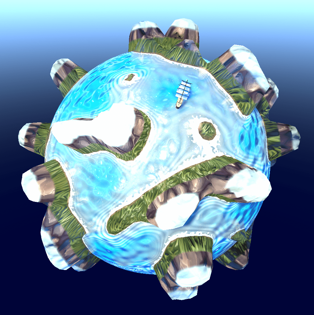
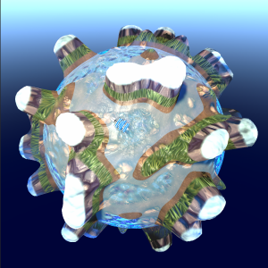
In this tutorial we will create a nice stylised procedural water shader that will be ideal to use together with the procedural planets shader created in the Unity Shader Graph Procedural Planet Tutorial.
We will create this water shader using Unity’s easy to use node-based shader creation tool Shader Graph..
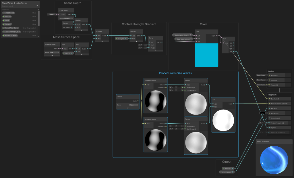
By sampling a colour gradient node with the depth/distance from the surface of the water to the underlying planet’s geometry we can create deep looking water bodies:

We can create waves with procedural noise by multiplying the output of two noise nodes together and by sampling the noise nodes with positions that move in opposite directions:
We can also use the calculated surface depth value to create convincing looking froth that goes around the coastlines:
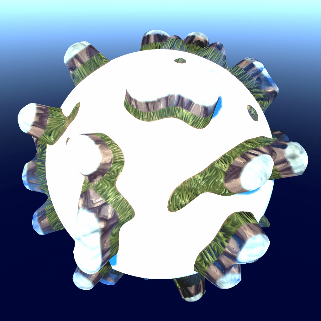
As a little extra experiment, if we use the water shader alongside with the procedural planet shader created with the Unity Shader Graph Procedural Planet Tutorial we can use noise with the same settings as for the planet shader, to create convincing looking coast wave ripples:

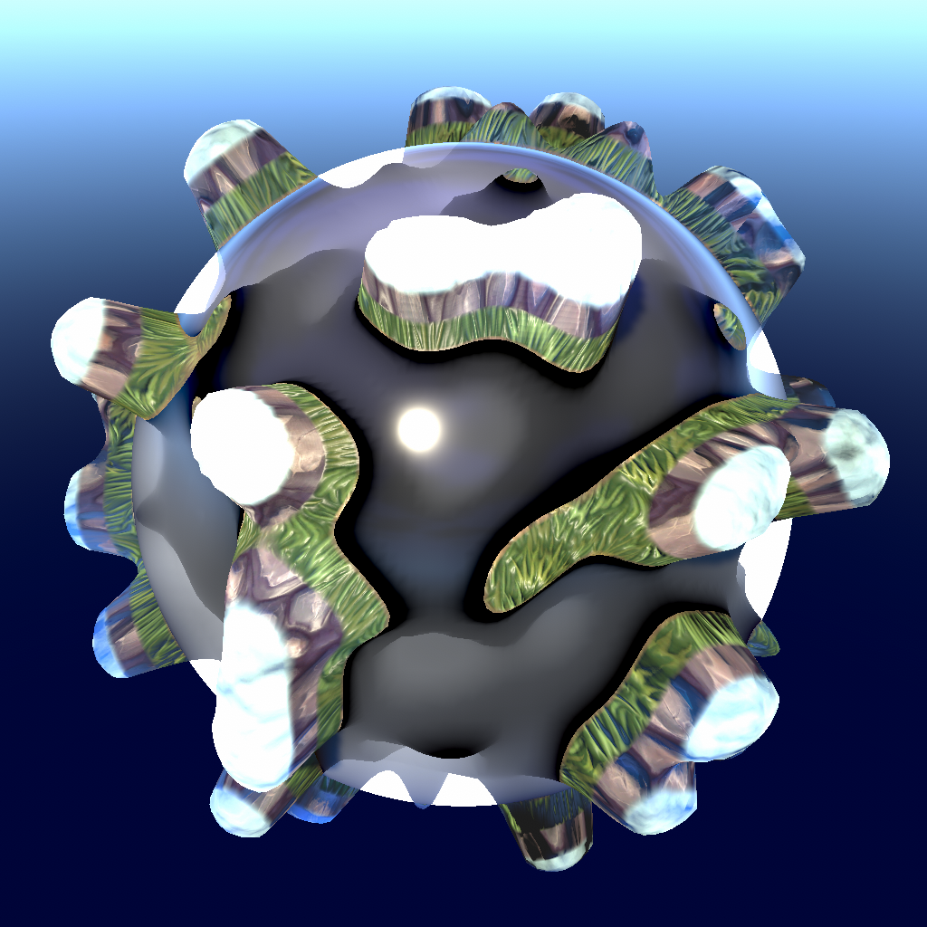
In the end we can create many different looking water materials with this shader that we’re going to create just by choosing different color, transparency, metallic and smoothness values:

By doing this tutorial you will learn:
- How to calculate the depth from the water surface to the underlying geometry.
- How to sample a color gradient with the depth value to create ultra deep looking water.
- How to generate waves with textures.
- How to generate waves with noise.
- How to use noise and the water depth value to generate froth.
- How to use the same noise as the planet’s terrain for an edge ripples effect.
Because we’ll be using Unity’s node-based Shader Graph no code-writing experience is required but we will not go over the basic fundamentals of using the Shader Graph system so if you’re completely new to using Shader Graph then I recommend looking over here first:
https://unity.com/shader-graph
This tutorial was written using Unity 2020.3.18f1 LTS using the URP (Universal Render Pipeline) but should also work with the HDRP and with Unity versions 2020.x.x and later releases.
0.1 Tutorial Materials
For the planet
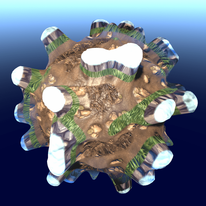
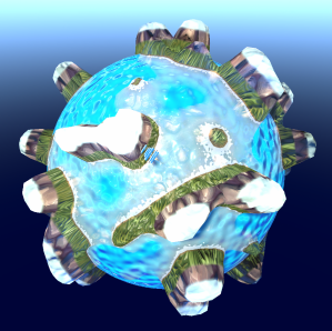
For the planet’s geometry this tutorial uses the CubeSphere from the Procedural Planet Tutorial :
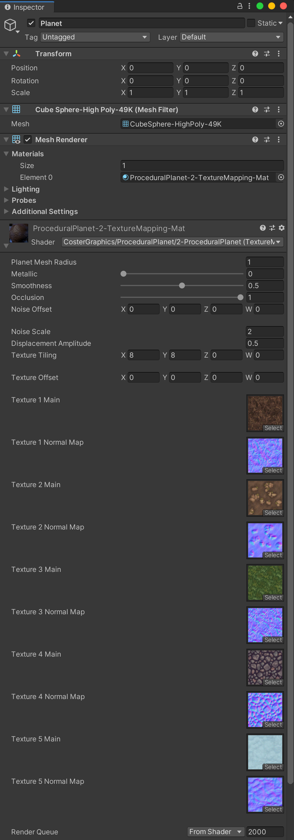
For the planet’s terrain shader this tutorial uses a shader created in the previous Unity ShaderGraph Procedural Planet Tutorial. To keep the example simple the planet in this tutorial doesn’t use the fully completed procedural planet shader but only the shader from step 2.2 with only one noise type, displacement and texture mapping applied:
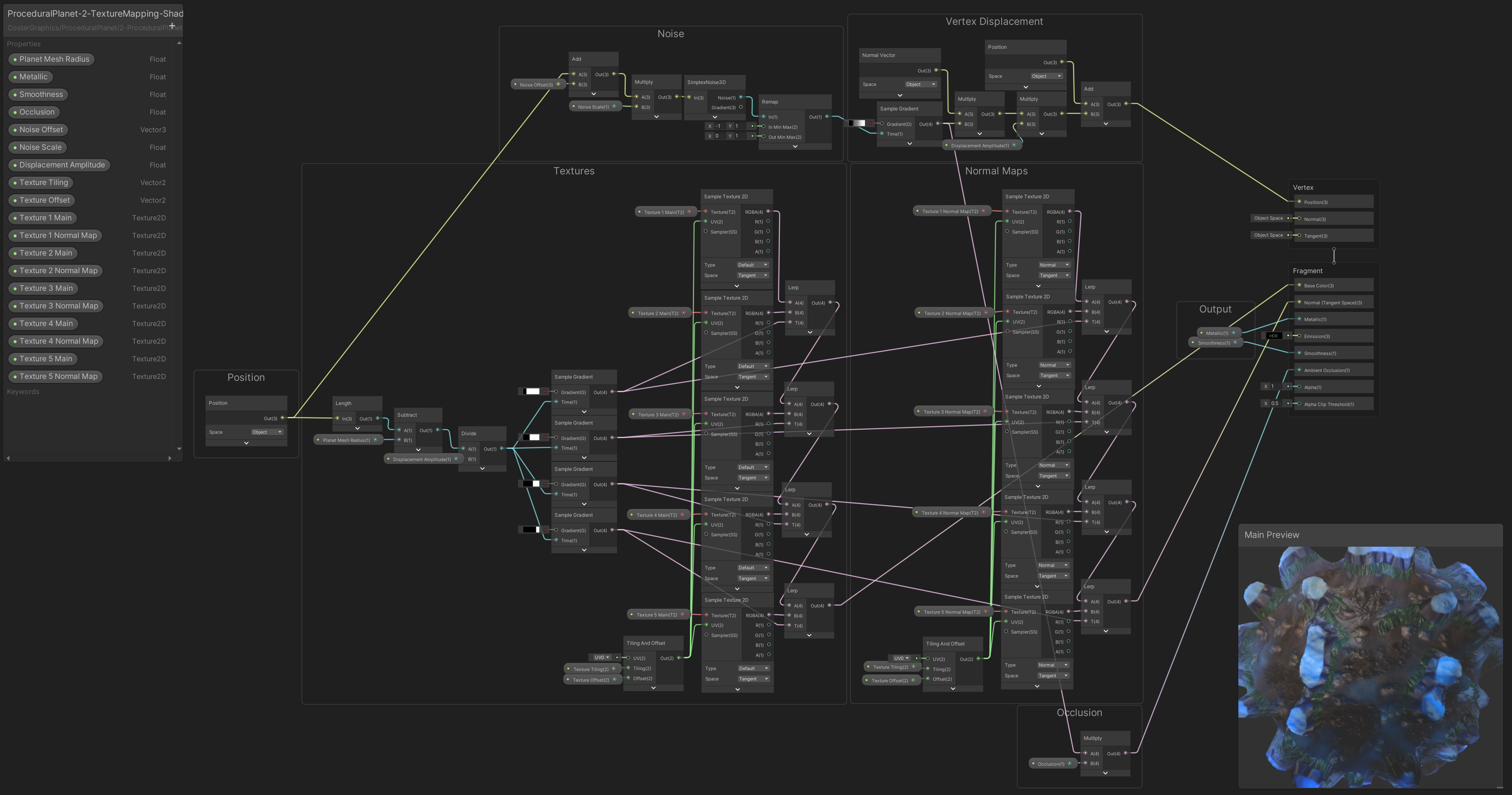
So if you want to create the exact same planet then follow the Unity ShaderGraph Procedural Planet Tutorial tutorial up to step 2.2 first to create the shader yourself or download the step 2.2 shader from below:
Below you can see the settings used for the planet’s material, the textures used are free ‘stylised’ terrain textures downloaded from the Unity Asset Store :
Stylized Terrain Textures :
https://assetstore.unity.com/publishers/16677
For the water

For the water mesh this tutorial uses a higher poly count UV sphere created with Blender with a little over 16K triangles that you can download below, just so that the sphere will look rounder when scaled up:
For waves that are based on a normal map texture this shader uses a seamless Perlin noise texture:

For waves that are based on procedural noise this shader uses a custom SimplexNoise3D node and for a ripples effect this shader uses a custom PingPong01 node which can be downloaded from here:
Unity Shader Graph Custom Function Nodes Collection
0.2 Setting up the scene
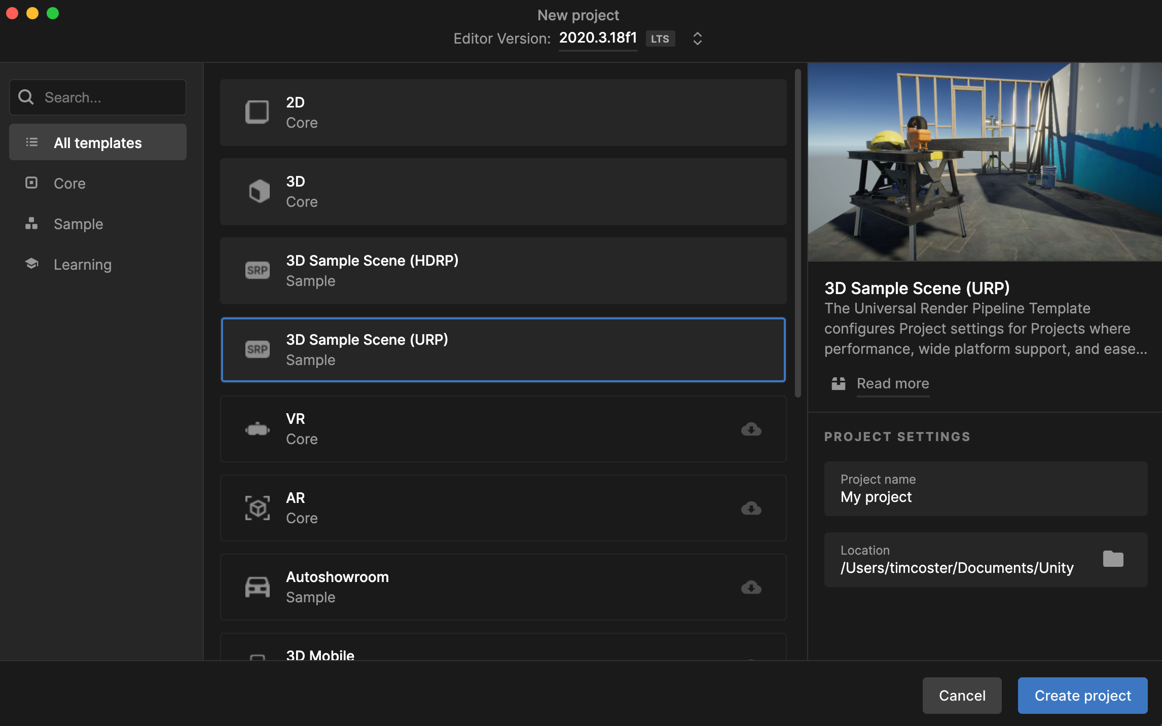
Open the Unity Hub and create a new Unity Project using the 3D Sample Scene (URP) template if you haven’t already:
Create a new Scene by pressing File > New Scene.
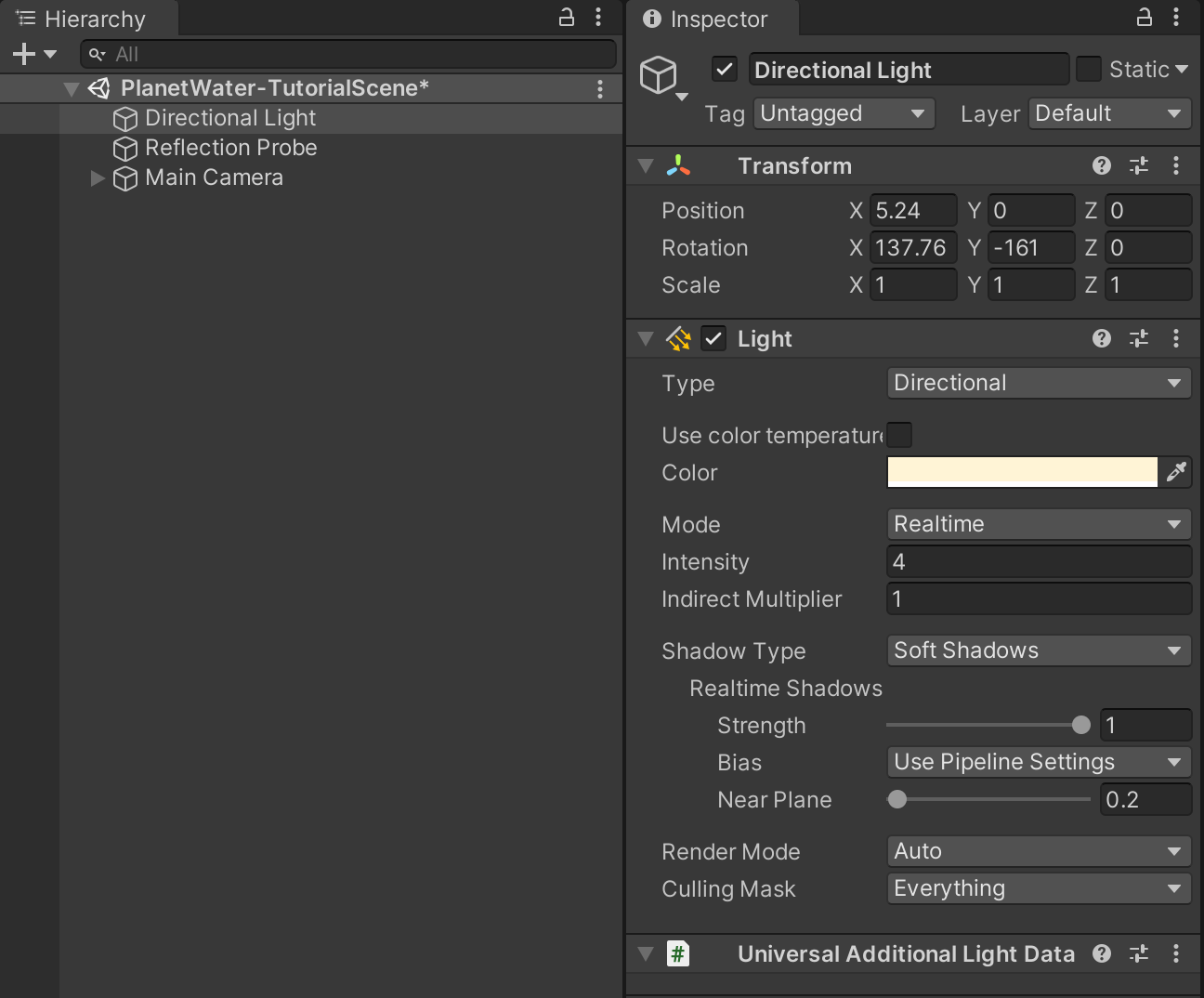
Select the Directional Light (the sun) in the Hierarchy view and set Intensity to four
Create a new Scene by pressing File > New Scene.
Select the Directional Light (the sun) in the Hierarchy view and set Intensity to 4:
Add a Reflection Probe to the scene so we can see reflections of the sky on the water surface by selecting GameObject > Light > Reflection Probe:

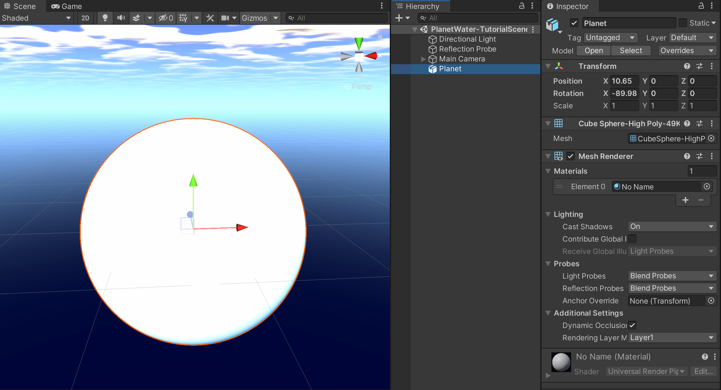
Create the planet terrain GameObject by dragging the CubeSphere-HighPoly-49K.fbx model from the Project view into the Hierarchy view and by rename it to Planet:
Right-Click in the Project view and select Create > Material to create a new material for the terrain of the planet (if you’ve downloaded the terrain shader then you can use the material from the package)
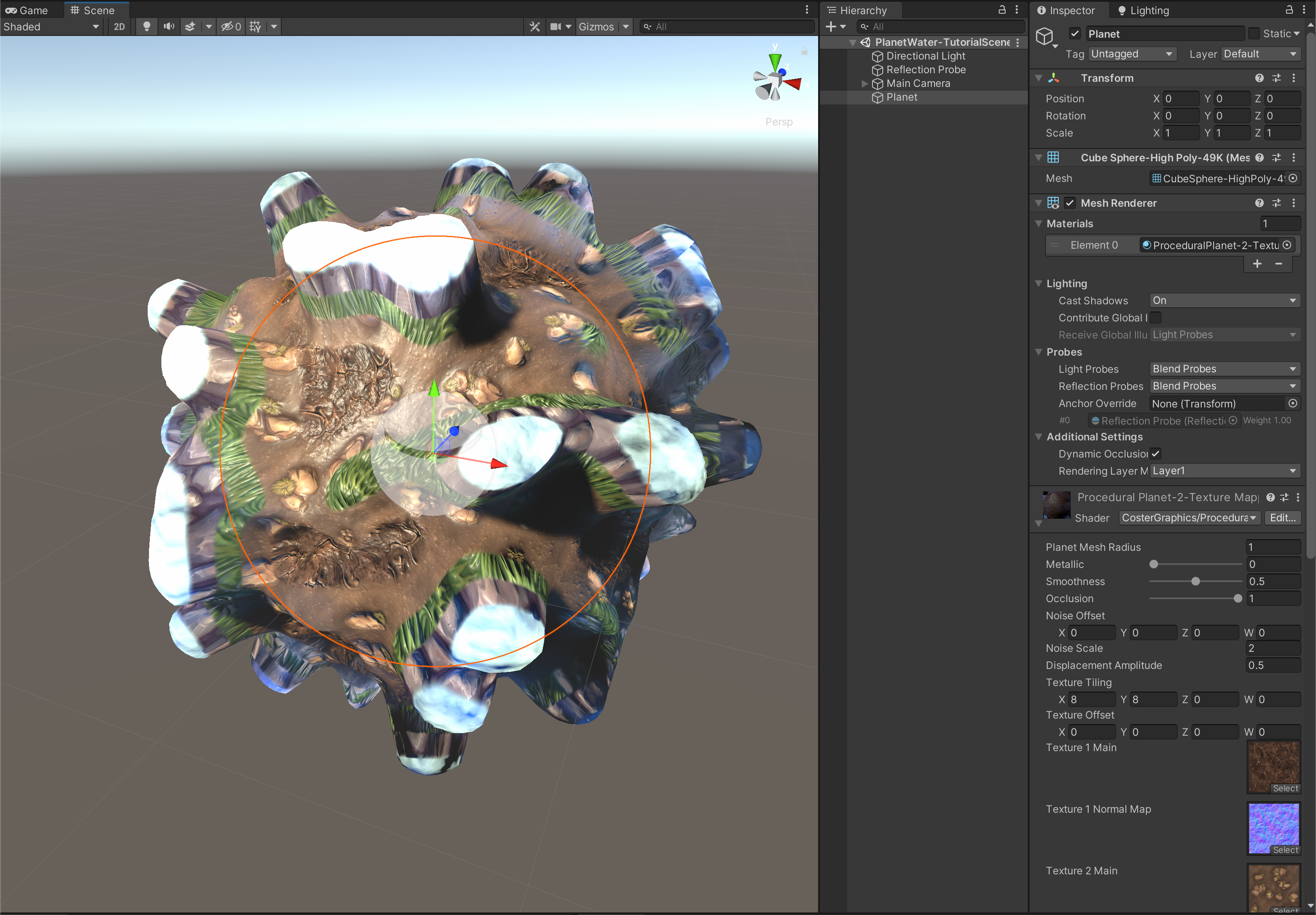
Select the Material en set the shader that it uses to ProceduralPlanet-2-TextureMapping-ShaderGraph in the Inspector. Simply type ‘TextureMapping’ inside the search field to have it popup in the list.
Supply the material with some terrain textures if you want the terrain to look decent:
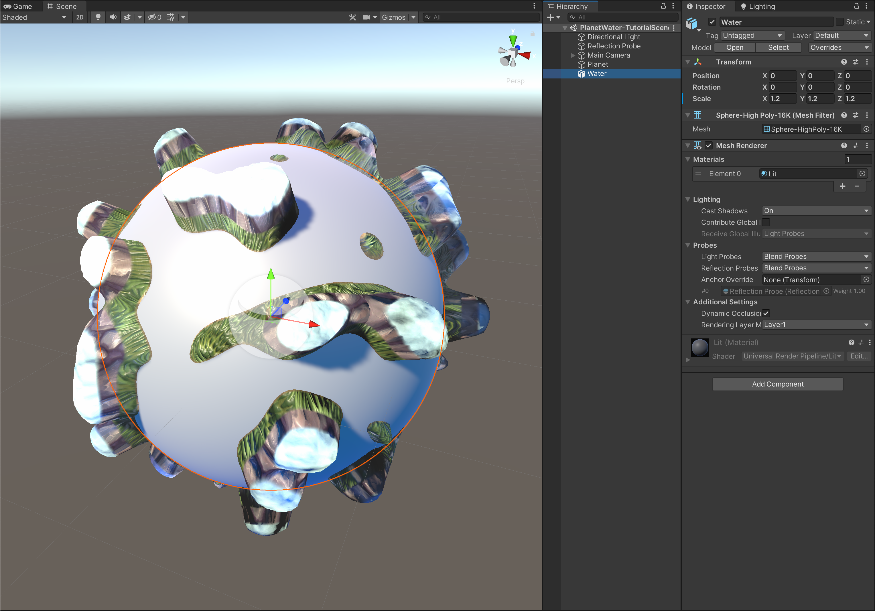
Create the sphere for the planet’s water by dragging the UVSphere-HighPoly-16K model from the Project view into the Hierarchy view. Rename it to Water and set the position of the water sphere and also the terrain sphere to 0,0,0 in the Inspector view to have them sit in the same place.
Set the Scale of the water sphere to 1.2 in the Inspector to make it a bit larger than the terrain sphere:
Create a new material for the water named PlanetWater-Mat and create a new Lit Shader Graph named PlanetWater-ShaderGraph by right-clicking in the Project view and selecting Create > Shader > Universal Render Pipeline > Lit Shader Graph.
Drag the shader file onto the material file in the Project view to make the material use the newly created Shader Graph.
To apply the material to the water sphere, drag the material onto the water sphere in the Scene view, or with the water sphere selected, drag it into the Materials slot of the Mesh Renderer in the Inspector view:

Double-Click on PlanetWater-ShaderGraph to open the Shader Graph window and make sure that the Graph Settings in the Graph Inspector window are as shown below so that the material will be rendered Transparant and will be Lit by Unity’s lighting system:
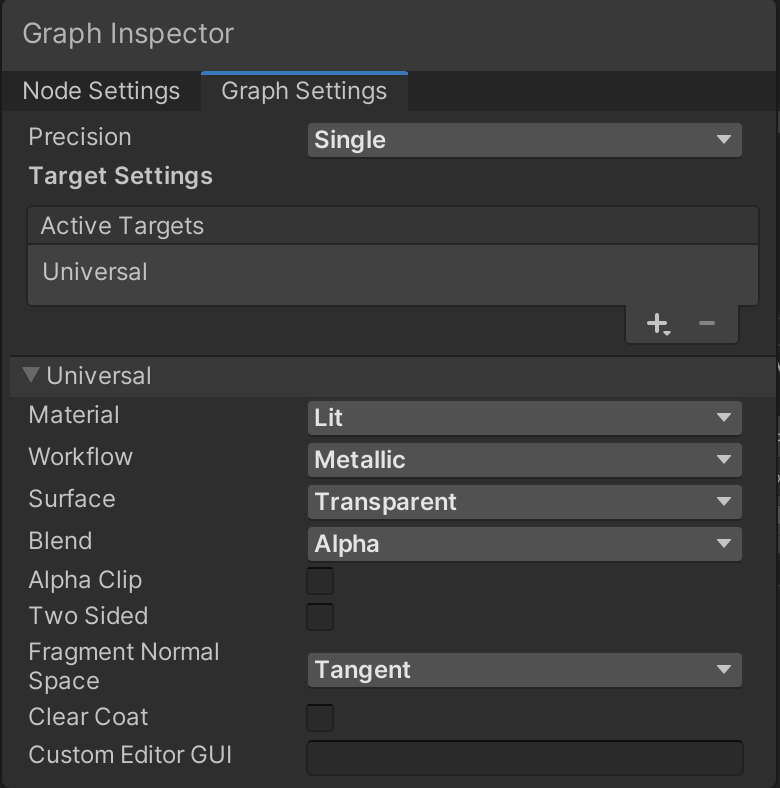
Great! We’re all set to start creating our planet’s water shader!
2. Water Depth
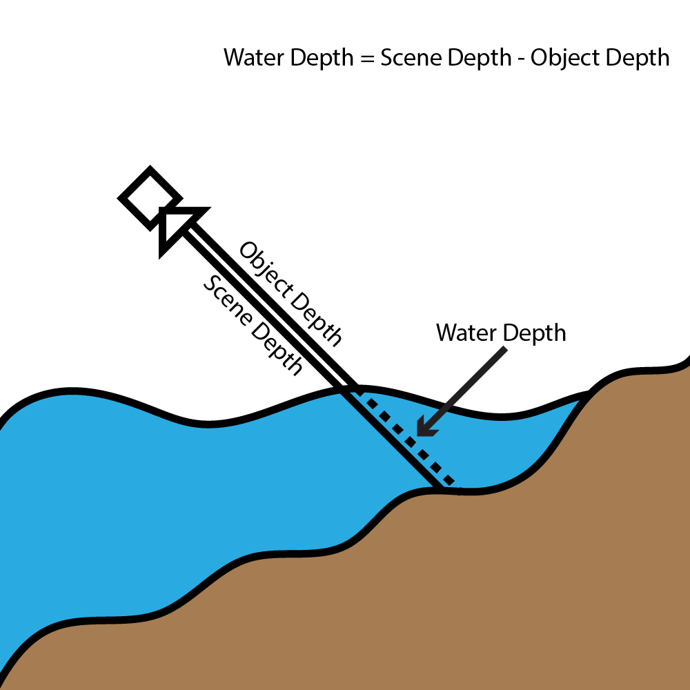
The first step in the process is to calculate the water depth. As you can see in the image below it is a relatively simple calculation. We only need to know two things in order to get a depth value below the water surface, the Scene Depth and the Object Depth. By subtracting the Object Depth from the Scene Depth we get a value for the water depth which is the distance from the surface of the water to the underlying planet’s geometry:
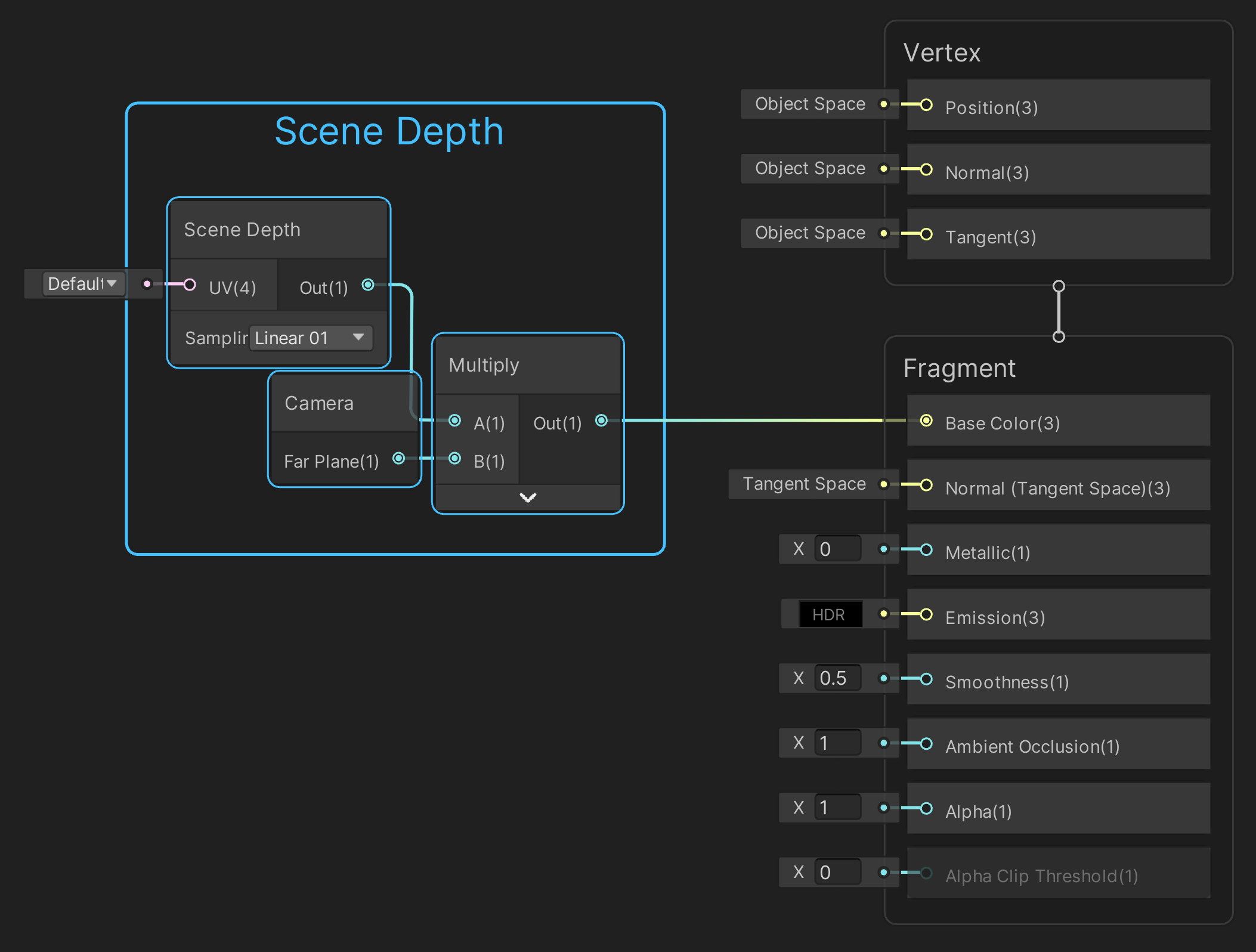
We can get the Scene Depth by using the Scene Depth node set to sample it Linearly from 0 to 1 and then by multiplying the Scene depth with the camera’s far plane distance (the distance at which scene geometry get’s culled off by the camera) we make sure the scene depth image that we get is correctly spread out over the distance at which the camera still renders geometry:
To get the Object Depth or the position of the mesh in screen space we can use the Alpha channel of the Screen Position node. By also adding a float variable/property for Depth we can adjust how strong the depth gradient will be. Float properties for Metallic and Smoothness were also added to the black board:
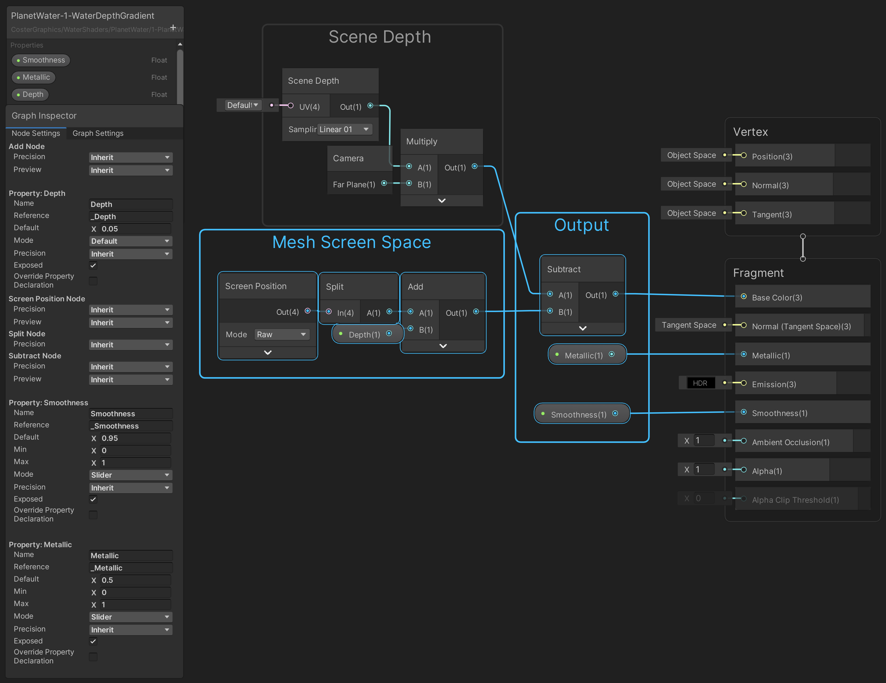
With this setup we now have a depth gradient that looks to be inside of the water sphere (but it is still only on the surface) that goes from deep (white) to shallow depth (black). Now this is something we can work with!:
If we want further control over the Strength of the depth gradient we can now multiply the output by a float value for Strength, so create the Strength float property on the Shader Graph Blackboard and Multiply the output of the depth calculation by it. Also Clamp the entire calculation to 0 min and 1 max, so that we can’t have a depth that is negative or above 1. We can give Strength a default value of around 4 and we can set the property Mode to Slider with 0 for the min value and 10 for the max value, for ease of use :

To give the water a pretty color we can Lerp (linearly interpolate) from a shallow water color to a deep water color over the length of the depth gradient so create two color variables on the blackboard and plug them into a Lerp node, then plug the output of the Gradient into the T (time) input of the Lerp node. To get control over the opacity of the water we can split the output of the Lerp node and use the alpha channel for the Alpha output:

With this setup the water will have a nice looking tropical island color blue!:

3. Waves
There are two easy ways that we can produce waves, the first is by using a normal map texture with a noise pattern on it, and the second is by using procedurally generated noise instead of a texture file. The first method is the cheapest but has the downside that there will be obvious texture stretching visible at the pole areas. The second method using procedural noise is more expensive but because with 3D noise we can use the position of the fragment in space to sample the noise with, so there will be no texture stretching at the poles. We can decide for ourselves what is best to use based on what project we use the water for. Keep in mind that both of the methods use the Normal output of the Shader Graph so the vertices of the mesh are not actually displaced by the waves, which is fine for planets that are only seen from a distance.
3.1 Normal Map Texture Waves
First create two properties on the blackboard of type Texture2D for two normal map textures and drag the downloaded Normal Map texture into the Default texture slots of both properties in the Graph Inspector. Set the Mode of both of the Texture2D properties to Bump.
Also create two Vector2 properties for texture tiling on the blackboard and give them default values of 5 on the x-axis and 5 on the y-axis for small looking waves.
Add two Tiling and Offset nodes, two Sample Texture 2D nodes and an Add node to the Graph.
Create the following setup and make sure that Type on the Sample Texture 2D nodes is set to ‘Normal‘ :
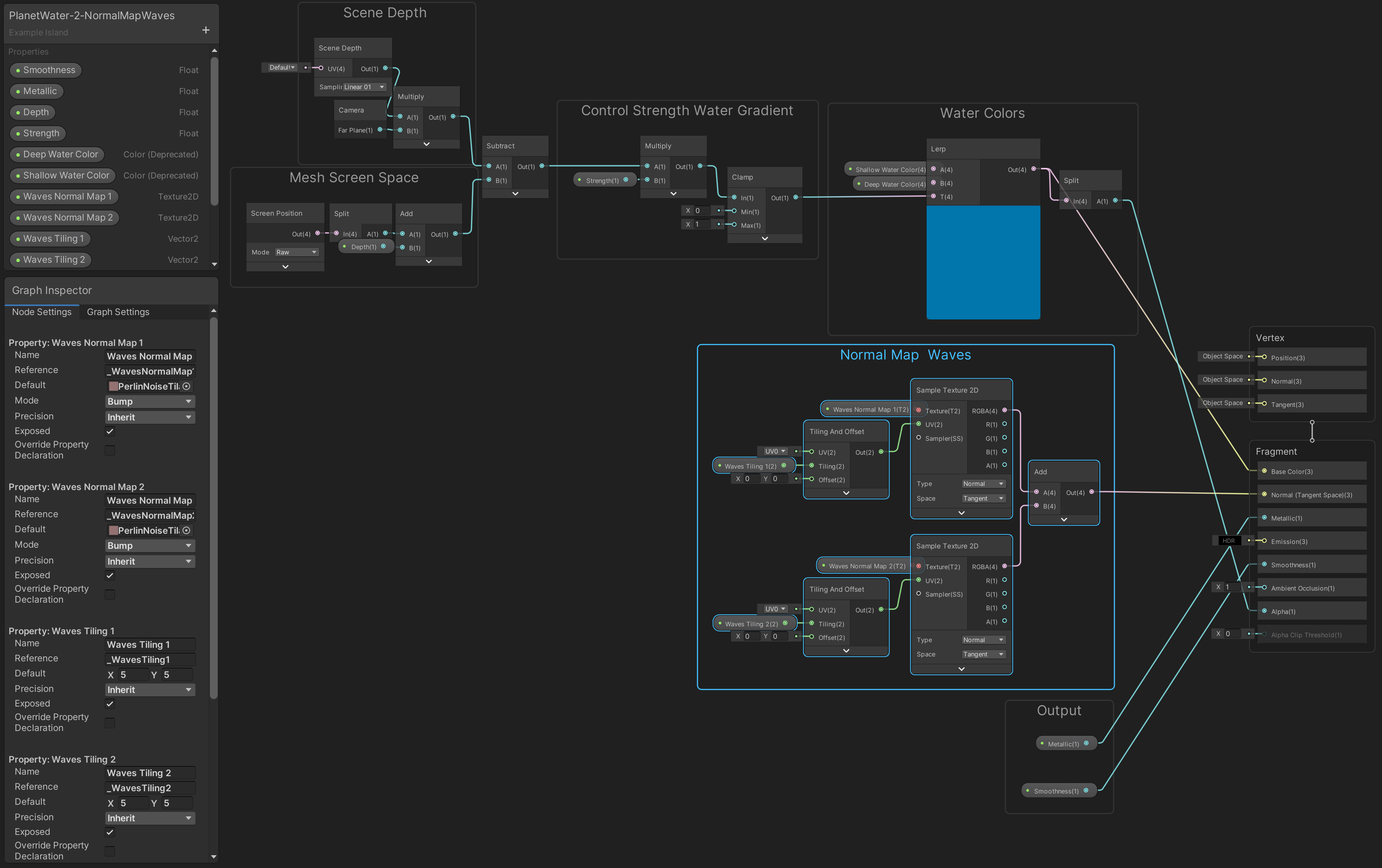
With this setup we’ve added two normal map textures on top of each other and outputted them to the material. Because we use the same texture and Tiling for both of the Waves Normal properties it looks like there is only one map applied but if you change the Tiling value for one of the Tiling and Offset nodes you will see that there are indeed two.
The water surface now looks bumpy but the created waves don’t move yet. To make the waves move first add two new Vector2 type properties to the blackboard for Waves Speed 1 and Waves Speed 2. Set the default values for Waves Speed 1 to 0.1 on the x-axis and 0.1 on the y-axis and set the default values for Waves Speed 2 to -0.1 on the x-axis and -0.1 on the y-axis so that the second texture will move in the opposite direction as the first. Add two Multiply and a Time node to the graph and create the following setup:
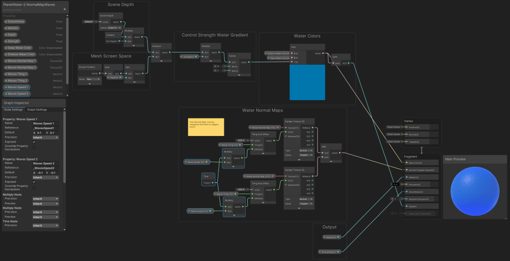
If you save the graph now you will see that by adding the time multiplied by a certain speed to the texture Offsets we have created a realistic looking waves texture for our planet’s water.
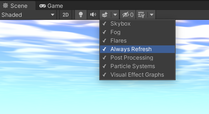
If you want to see the full wave effects in motion while operating in the Scene view then make sure that the Scene view camera is set to ‘Always Refresh’ in the camera effects tab:
The next step is to control the strength of the normal map waves and we can do this by adding a Normal Strength node to the graph. We could simply set the strength to a certain value but if we also use the calculated water depth value for the strength of the normal maps then we can create higher waves for the deeper parts of the oceans and low waves for the shallow parts. We can do this by linearly interpolating the strength of the waves over the water depth.
To create this effect first add a float type property to the blackboard for Waves Strength with a default value of 1. Then add a Normal Strength node and a Lerp node to the graph and create the following setup:

Save the graph and you will see that the waves now gradually decrease in strength towards the coastlines of the planet:
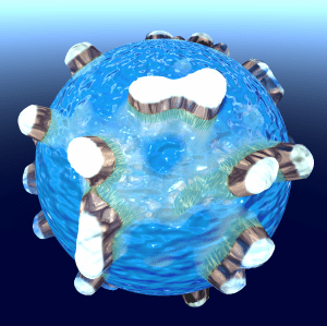
The planet now has moving water waves but if you look at the top and bottom pole areas of the water sphere you will see that the pattern of the normal map texture looks very compressed. This may not always be a problem for instance if the planet terrain has a landmass that covers the pole areas of the water sphere or for regular flat water surfaces but for a procedurally generated planet we might want to play it safe..
3.2 Procedural Noise Waves
To create waves on a spherical object without getting the obvious stretching/compressing around the poles we can use procedural 3D noise. Make sure you have the custom SimplexNoise3D node added to your project and if you want to keep the normal map texture wave function for future reference then keep a duplicated Shader Graph backup file of the water shader up to this point.
Otherwise feel free to remove the the waves nodes setup from the graph and also the Waves Normal Map texture2D and Waves Speed properties from the blackboard since we don’t need those anymore.
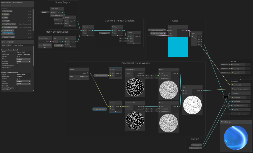
Add two SimplexNoise3D nodes, two Remap nodes a Position node and an Add node to the graph and create the following setup:
By using the position of the fragment on the water sphere’s surface to sample the 3D noise we ‘get’ the noise in that position. Because the SimplexNoise3D node returns a noise value between -1 and 1 we have to remap it to go from 0 to 1 to use the full range of the noise. By adding both the values of both SimpleNoise3D nodes we get the same effect as with adding two noise textures.
We now have a noise shape on the water surface but it is still very large so we have to scale it. We can do this by multiplying the position that we use to sample the noise with so add two Multiply nodes and create two float type properties on the blackboard named Waves Scale 1 and 2 with a default value of 10:
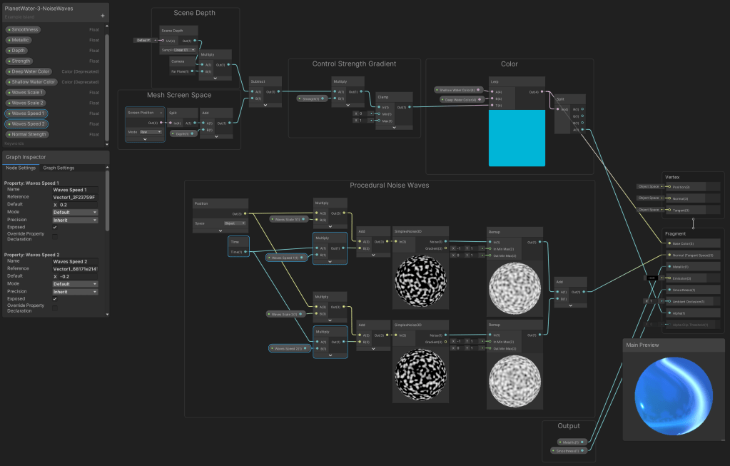
To make the noise patterns move we can simply add Time multiplied by speed to the position that we are sampling the noise with so add two add, two Multiply and a Time node to the graph. Also add two float properties to the blackboard for Waves Speed 1 and 2 with default values of 0.2 and -0.2 and create the following setup:
We now have scaled the waves and made them move but what we have now can be thought of as a bump or height map instead of a normal map so we have to convert the height map to a normal map. Add two Normal From Height nodes to the graph and just as with the two normal map textures method we can Lerp the strength of the waves over the water depth so add a Lerp and a Normal Strength node and create the following setup:
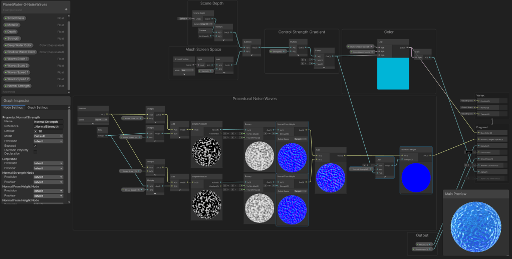
We now have procedurally generated waves without the obvious stretching around the poles!:
3. Water Edge Froth
In this step we are going to create edge foam/froth around the coastlines of our planet and we can do this again by using the water depth value, but because we want to be able to control the froth separately from the water color we’re going to create a separate depth calculation setup for the froth first…
Just like the water depth calculation we start the edge froth calculation with subtracting the Object Depth from the Scene Depth and by subtracting a value from the Object Depth we can then control the width of the froth:
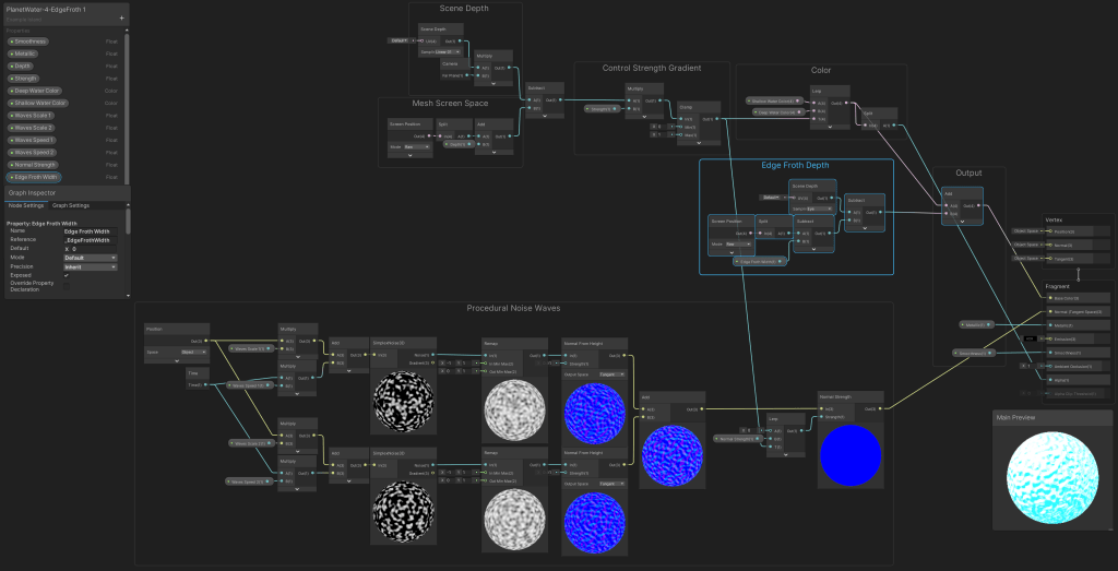
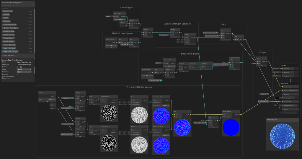
To get control over the strength of the edge froth we can Lerp from zero to a value for strength using the Lerp node. A default value for edge Froth Strength that works well with the size of the planet is around -30:
For the froth itself we can do a calculation similar to what we did for the waves. The difference with the waves is that we want to add the output of the calculation to the Base Color output of the shader and not to the normal. A Step node is used to cut off the froth noise at a fixed point and we can use new separate properties for Froth Scale and Froth Speed:
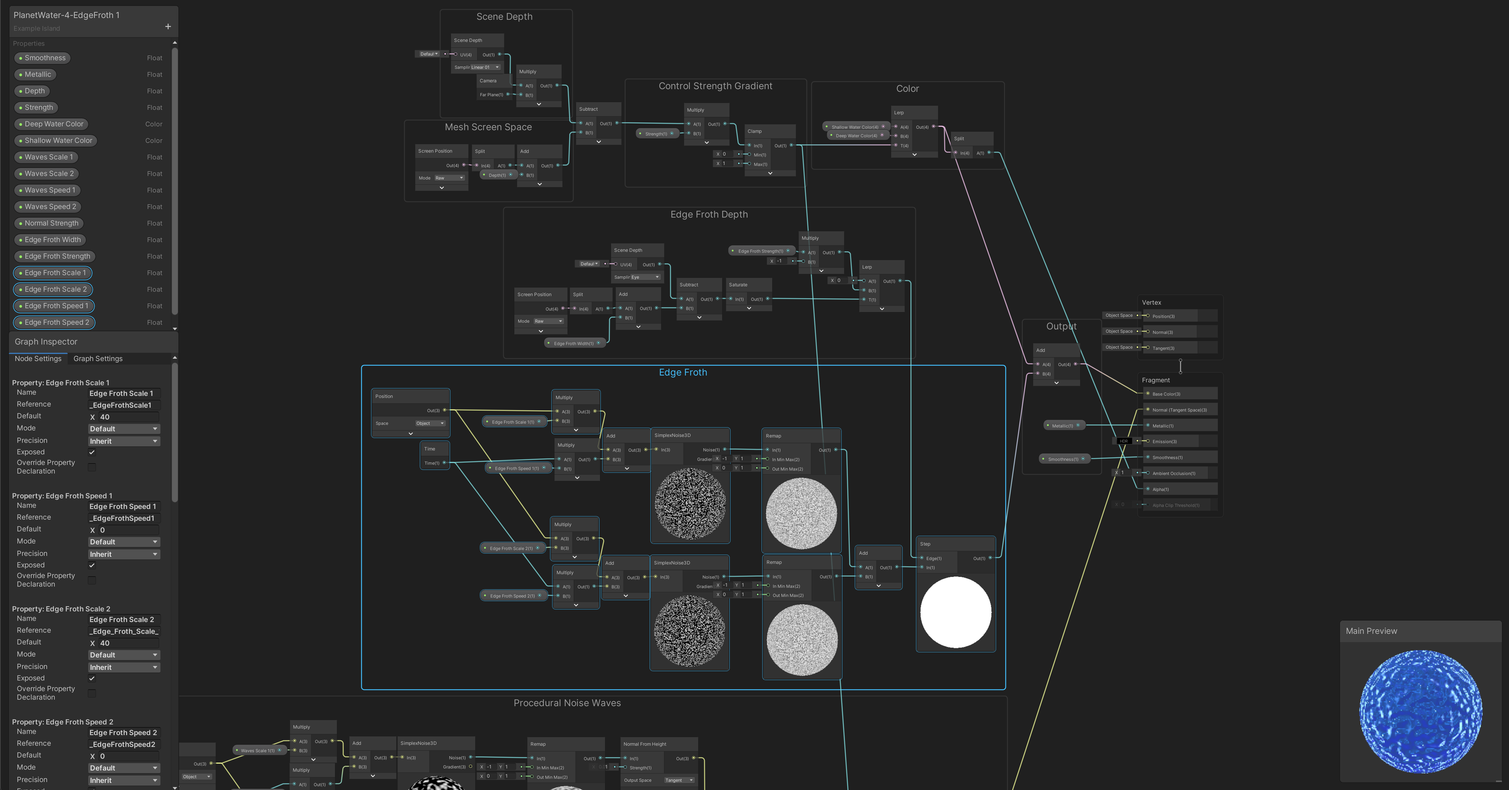
To get control over the edge froth smoothness we can use SmoothStep instead of Step and add a property for Edge Froth Smoothness. To give the froth a different color we can just multiply the output by a (HDR) Edge Froth Color property:
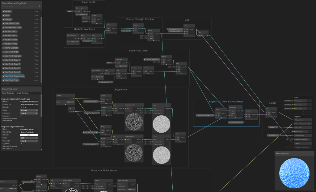
The complete Procedural Planet Water shader up to this point:

And what the froth now looks like:
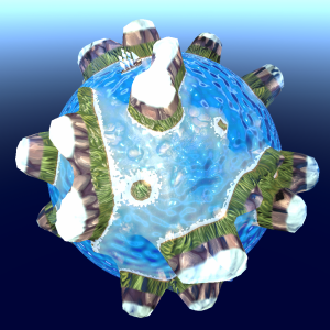
4. Water Edge Ripples
Now that we’re using procedurally generated noise for both the waves and the froth why not use the noise to create some wave ripples that spread out from the deeper parts of the oceans towards the coastlines. I personally like this effect because keen eyes will have noticed that using depth for froth and deep looking water is not perfect. Because we are using the camera’s depth texture the shallow parts of the terrain that are behind our camera’s view are not calculated as having depth so the depth effect sort of ends around the corners of the visible terrain. But if we use the same noise calculation settings for some water ripples that we use for the terrain we can have a ripple effect that actually does go around the corners. Keep in mind that this only works well if we use the same noise calculation for the water ripples that we use for the planet’s terrain shader because we want the ripples to align with the terrain.
To create this effect we sample noise with the fragment’s position in object space in the same way that we sample the noise for the planets terrain, so make sure that the noise for the terrain and the water edge ripples use the same offset values. For the example the values of the vector3 Edge Ripples Offset property of the water shader and the vector3 Noise Offset property of the procedural planet shader are both 0,0,0.
The Edge Ripples Scale property of the water shader and the Noise Scale property of the terrain shader should also be the same, for the example they were set at 2.
The Edge Ripples function draws the sampled noise on the water sphere first and then it ‘ping pongs’ the value to create a rippled lines effect instead of just smooth noise:
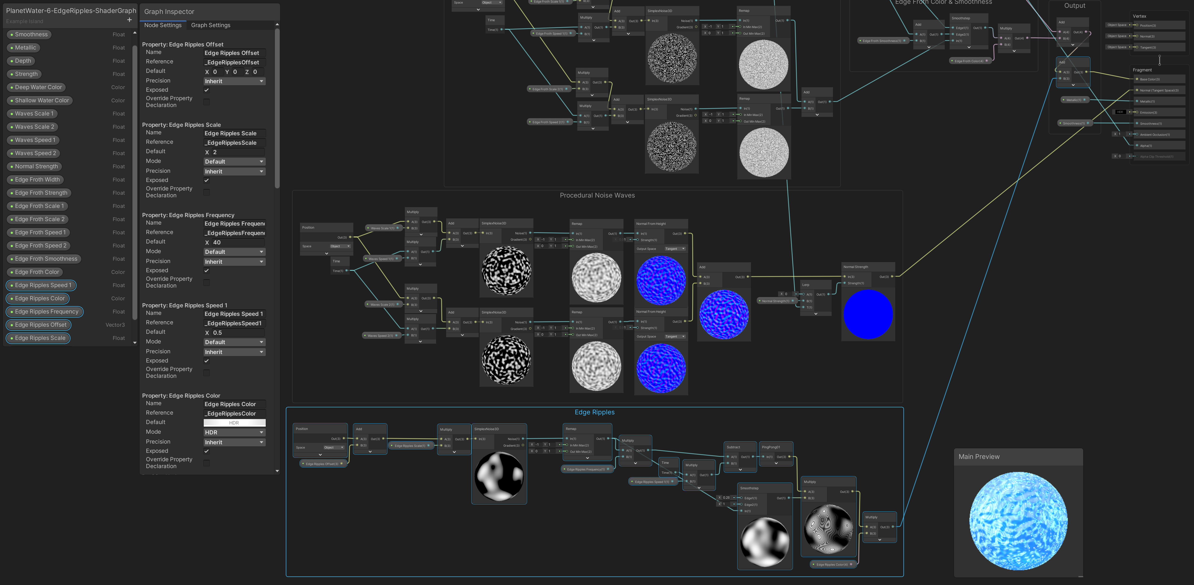
What the final edge ripple effect looks like:

5. The Complete Shader Graph

Reference Material
Downloads
Unity Shader Graph Procedural Planet Water Tutorial Package

BUY ME A COFFEE
Donate $5 to buy me a coffee so I have the fuel I need to keep producing great tutorials!
$5.00
Hey fellow Shader Graph enthusiast!
Looking for a highly versatile and easy to modify system for rendering professional Screen-Space Edge-Detection based selection Silhouette Outlines, Contour Outlines and Overlays, around and onto any 3D model in the Unity Game Engine?
Checkout CosterGraphics 🔳 Outline System Pro if you haven’t already!
