
Unity ShaderGraph Procedural Skybox (Tutorial)
Create the sun and the sky,
And the stars and the clouds,
Add them all up,
And turn day into night
0.Introduction
Turns out.. it’s surprisingly easy to start creating your own custom skybox shaders with Unity + ShaderGraph…
In this tutorial we’ll build up a fully customizable skybox by creating functions in ShaderGraph for each different layer the skybox consists of, starting with the colors of the sky, then we’ll add the sun and a layer for the clouds and the stars and blend between day and night by the rotation of the directional light in the scene.
This tutorial was written using Unity 2019.2.4f1 using the LWRP template and later upgraded to work with Unity2019.3.1f1 and URP.
The only real difference between the LWRP and the URP shader graph is that you have to enable ‘Two Sided’ on the Unlit Master output node.. See step 1.5.
1. Creating the Skybox Material
1.1 Create a new unlit ShaderGraph
Right click in the Project window and select Create > Shader > Unlit Graph
1.2 Create a new material
Create a new material in the Project window and drag the ShaderGraph on top of it to assign it to the material.
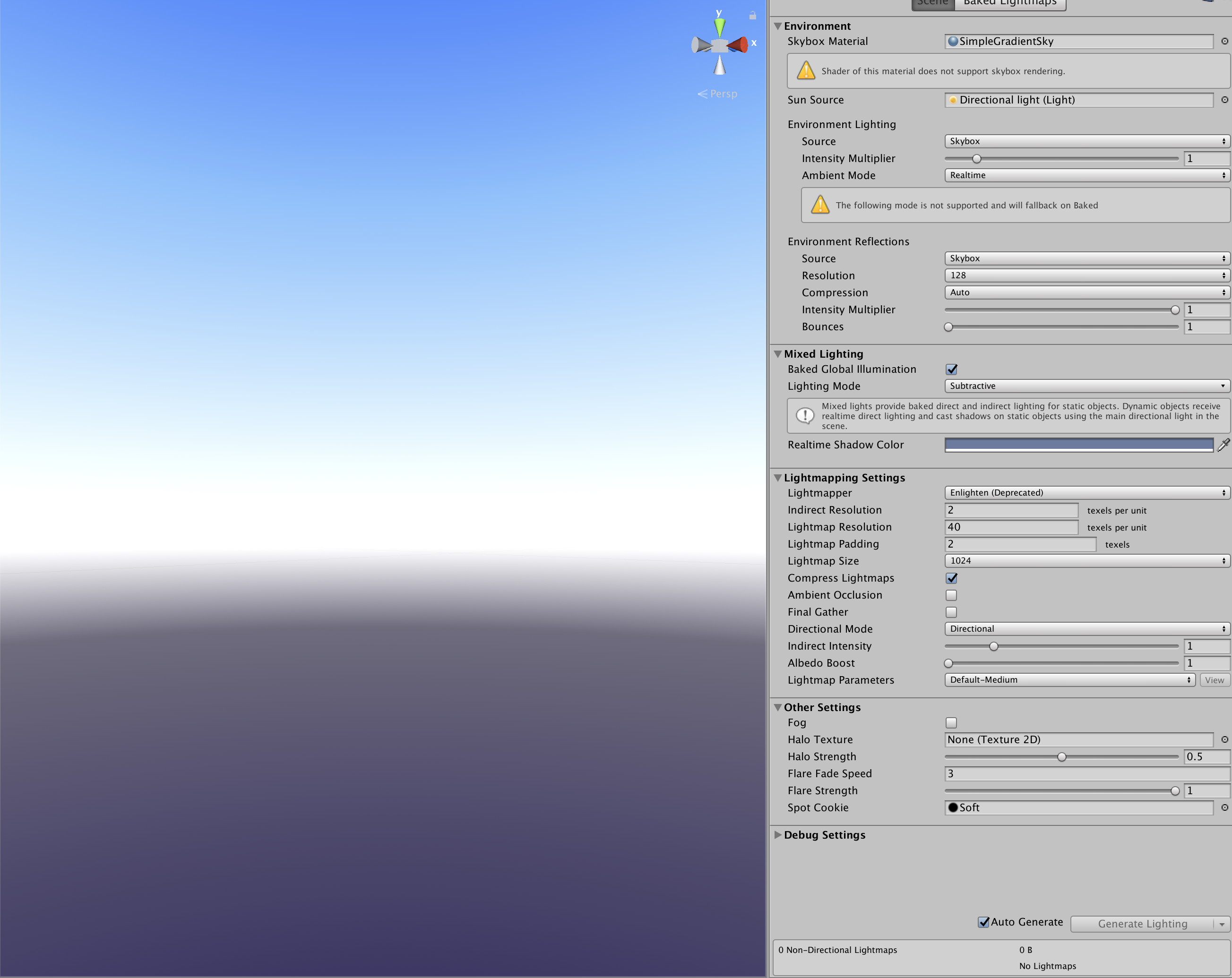
1.3 Assign the material to the skybox
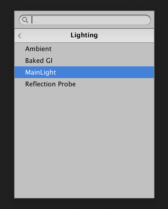
Open Window > Rendering > Lighting Settings and drag the material into the Skybox Material slot in the Environment settings.
1.4 Open the ShaderGraph
Double click on the Skybox ShaderGraph file in the project window to open the graph…
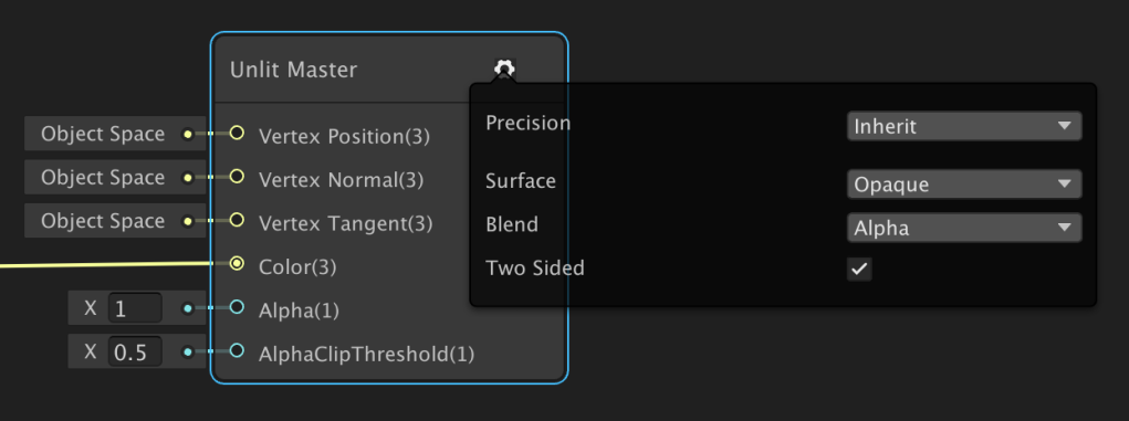
1.5 Unlit Master Node Settings URP
If you are using Unity 2019.3 and the URP then you have to enable ‘Two Sided’ in the unlit master node settings by clicking on the cogwheel icon:
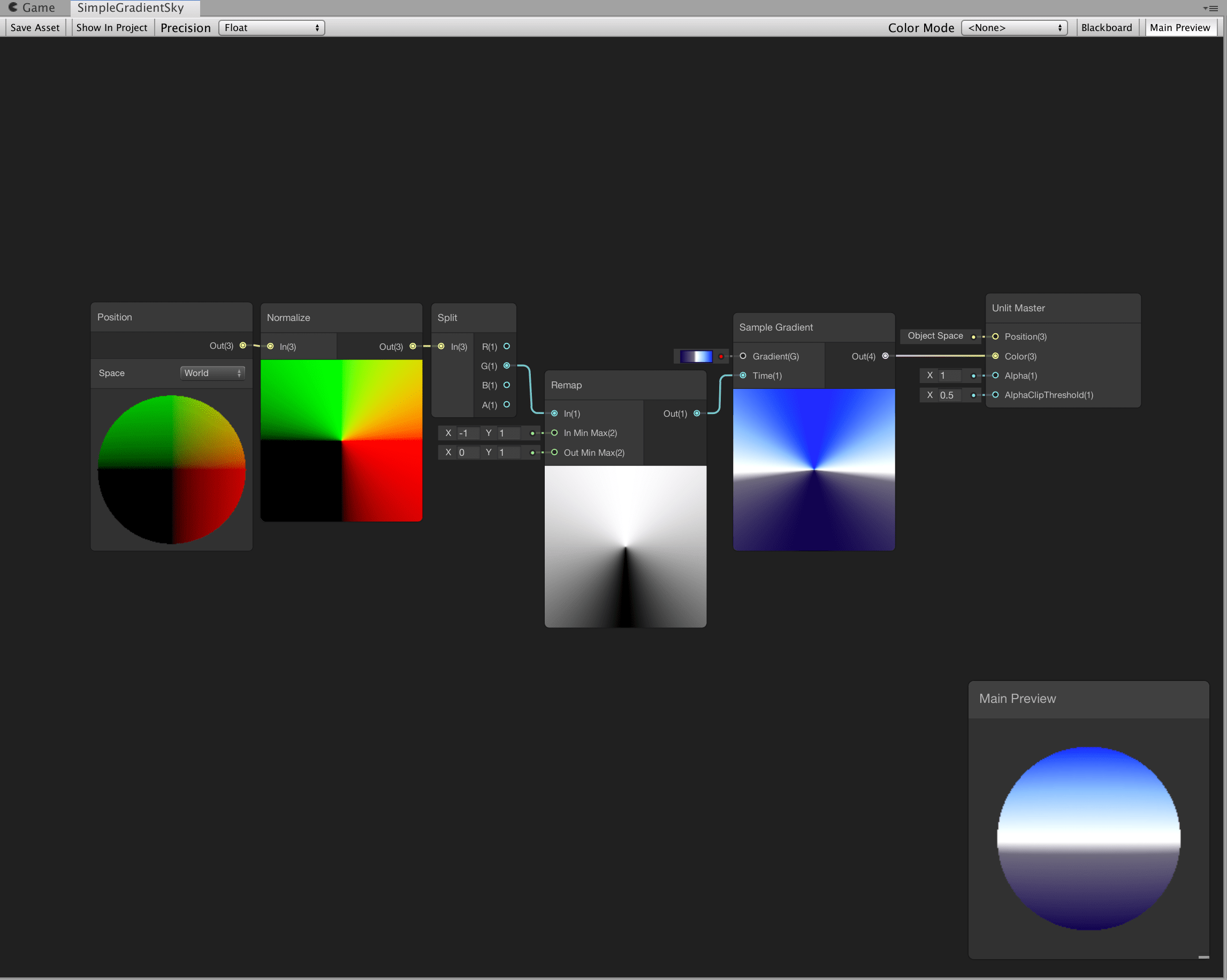
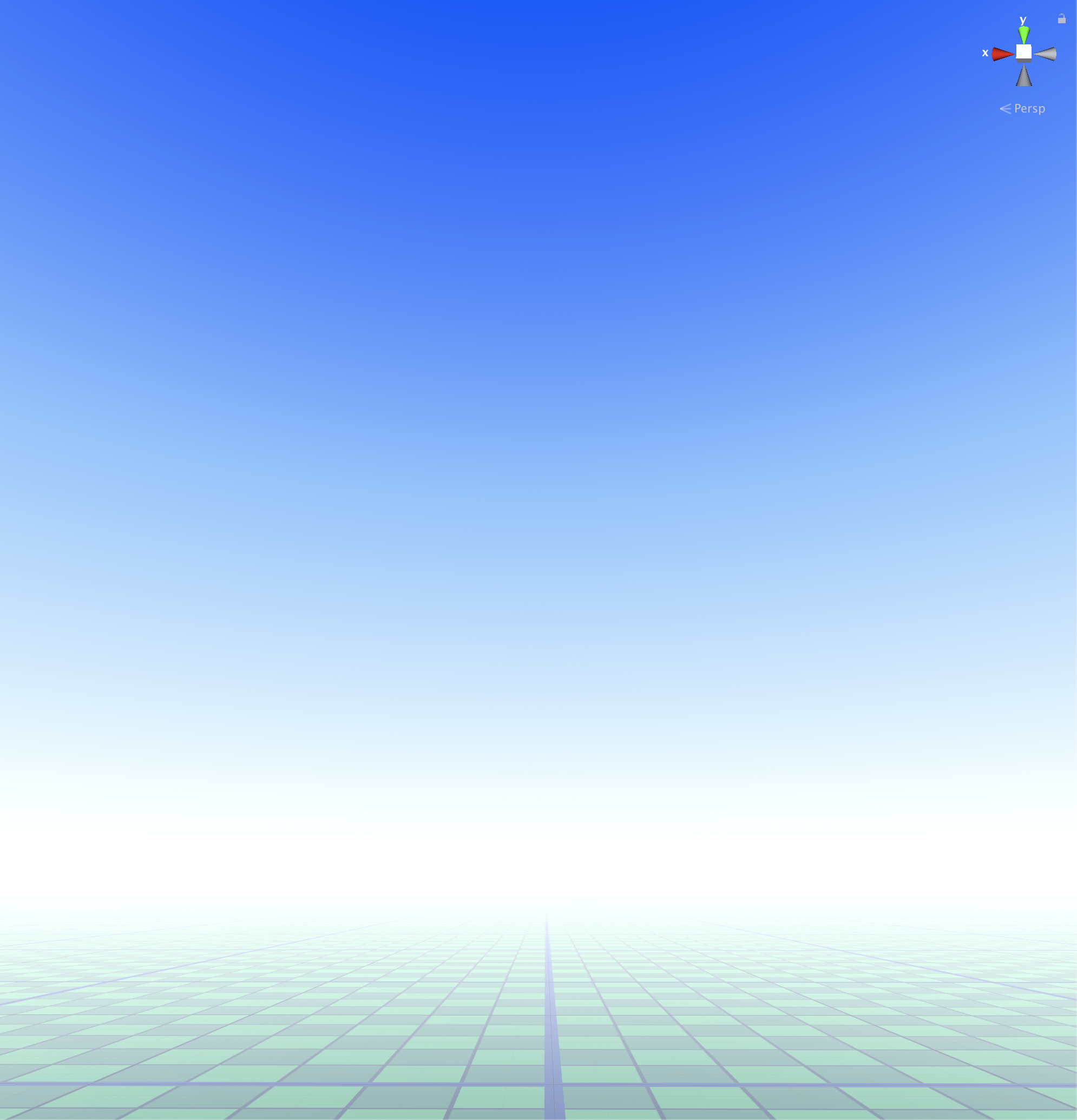
1.6 Simple gradient sky Test
Just to make sure everything works we can create a very simple gradient skybox by using the green channel (Y-axis) of the normalised world position and feeding that into a sample gradient node. The normalised world position ranges from -1 at the bottom of the world to 1 at the top center of the world so in order to plug that value into the time input of the gradient it needs to be remapped to a 0 to 1 range first:
It would be really great if we could use gradients throughout the entire skybox but at the moment gradients in ShaderGraph cannot be turned into exposed properties so for the sake of not having to open the graph to make adjustments and so that we can use the same shader for different materials we’ll use three separate color properties instead and blend between those..
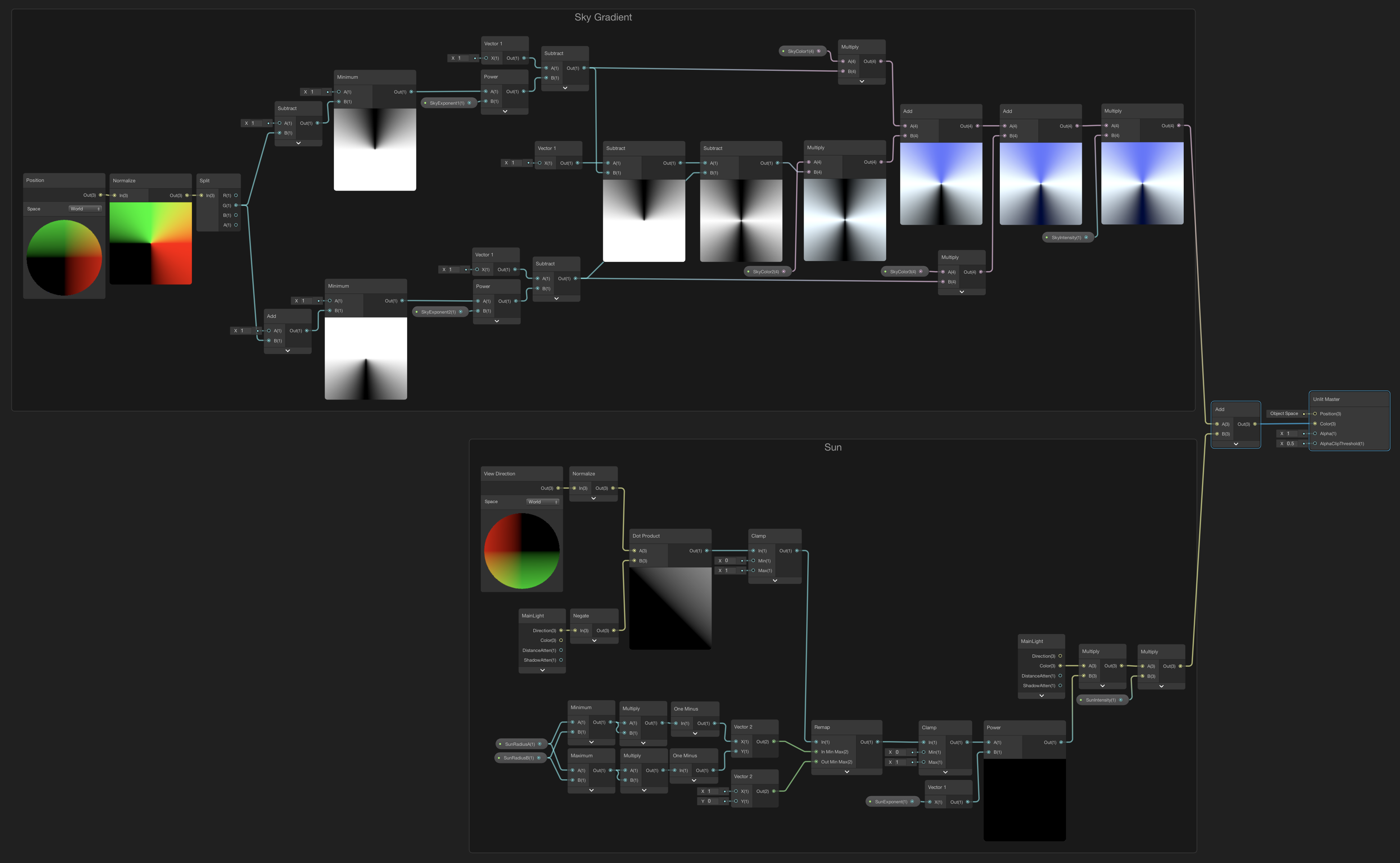
2. Adding a Sky Layer
This ShaderGraph nodes setup blends three exposed HDR color properties for the sky, horizon and ground. The softness of the gradient towards the horizon from the ground and from the sky can be adjusted with the Exponent1 and Exponent2 properties, the overall brightness with the Intensity property. By using HDR colors we can make the sky emit light coming from the middle horizon color for instance. Using HDR colors combined with a Bloom post-processing effect on the camera can make it look even better!:

3. Adding the Sun
To add a sun to a skybox that has its position based on the direction of a directional light in your scene, a custom ‘Main Light’ node that gets the direction of the Main Light in the scene has to be created first..
You can find detailed instructions on how to create this custom main light node (and custom nodes in general) in this Unity blog post (opens in a new tab).: blogs.unity3d.com/2019/07/31/custom-lighting-in-shader-graph…
The best way to create a custom node that we can reuse in other graphs as well is to create a Custom Function node first and then convert it into a Subgraph.
Both the custom node function .hlsl file and the SubGraph can be downloaded from here (see the Subgraphs and CustomNodes folders): github.com/Timanious/MyShaderGraphs…
Or if you want to create this custom node yourself, you can follow along with these instructions to create the Main Light node…
3.1 Create a Custom Function node
Right click in the ShaderGraph working area and create a new Custom Function node, you can find it under ‘Utility’:

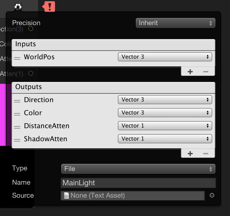
3.2 Add input and output parameters
Click on the settings cogwheel from the Custom Function node and add the following input and output parameters:

3.3 Function name
The name of the function inside of the .hlsl file that this node is going to use is called MainLight, type that into the Name field:
3.4 Adding an HLSL include file
As you can see the Custom Function node has the option to use a inline function if you switch the type to string, (see the Unity blogpost for more information about that) but using a separate HLSL include file gives us more flexibility, it can contain more complicated functions and you can keep them all organised in one place.
At the time of writing this, Unity doesn’t have a convenient menu item for creating an HLSL include file asset, so you’ll have to create it yourself, for example by creating a normal unlit .shader or .cs file and changing the file extension to .hlsl and removing the code from it..
Create a file named CustomLighting.hlsl, paste the code from below into it and save it :
#ifndef CUSTOM_LIGHTING_INCLUDED
#define CUSTOM_LIGHTING_INCLUDED

void MainLight_float(float3 WorldPos, out float3 Direction, out float3 Color, out float DistanceAtten, out float ShadowAtten)
{
#if SHADERGRAPH_PREVIEW
    Direction = float3(0.5, 0.5, 0);
    Color = 1;
    DistanceAtten = 1;
    ShadowAtten = 1;
#else
#if SHADOWS_SCREEN
    float4 clipPos = TransformWorldToHClip(WorldPos);
    float4 shadowCoord = ComputeScreenPos(clipPos);
#else
    float4 shadowCoord = TransformWorldToShadowCoord(WorldPos);
#endif
    Light mainLight = GetMainLight(shadowCoord);
    Direction = mainLight.direction;
    Color = mainLight.color;
    DistanceAtten = mainLight.distanceAttenuation;
    ShadowAtten = mainLight.shadowAttenuation;
#endif
}

void MainLight_half(float3 WorldPos, out half3 Direction, out half3 Color, out half DistanceAtten, out half ShadowAtten)
{
#if SHADERGRAPH_PREVIEW
    Direction = half3(0.5, 0.5, 0);
    Color = 1;
    DistanceAtten = 1;
    ShadowAtten = 1;
#else
#if SHADOWS_SCREEN
    half4 clipPos = TransformWorldToHClip(WorldPos);
    half4 shadowCoord = ComputeScreenPos(clipPos);
#else
    half4 shadowCoord = TransformWorldToShadowCoord(WorldPos);
#endif
    Light mainLight = GetMainLight(shadowCoord);
    Direction = mainLight.direction;
    Color = mainLight.color;
    DistanceAtten = mainLight.distanceAttenuation;
    ShadowAtten = mainLight.shadowAttenuation;
#endif
}

void DirectSpecular_float(float3 Specular, float Smoothness, float3 Direction, float3 Color, float3 WorldNormal, float3 WorldView, out float3 Out)
{
#if SHADERGRAPH_PREVIEW
    Out = 0;
#else
    Smoothness = exp2(10 * Smoothness + 1);
    WorldNormal = normalize(WorldNormal);
    WorldView = SafeNormalize(WorldView);
    Out = LightingSpecular(Color, Direction, WorldNormal, WorldView, float4(Specular, 0), Smoothness);
#endif
}

void DirectSpecular_half(half3 Specular, half Smoothness, half3 Direction, half3 Color, half3 WorldNormal, half3 WorldView, out half3 Out)
{
#if SHADERGRAPH_PREVIEW
    Out = 0;
#else
    Smoothness = exp2(10 * Smoothness + 1);
    WorldNormal = normalize(WorldNormal);
    WorldView = SafeNormalize(WorldView);
    Out = LightingSpecular(Color, Direction, WorldNormal, WorldView,half4(Specular, 0), Smoothness);
#endif
}

void AdditionalLights_float(float3 SpecColor, float Smoothness, float3 WorldPosition, float3 WorldNormal, float3 WorldView, out float3 Diffuse, out float3 Specular)
{
    float3 diffuseColor = 0;
    float3 specularColor = 0;

#ifndef SHADERGRAPH_PREVIEW
    Smoothness = exp2(10 * Smoothness + 1);
    WorldNormal = normalize(WorldNormal);
    WorldView = SafeNormalize(WorldView);
    int pixelLightCount = GetAdditionalLightsCount();
    for (int i = 0; i < pixelLightCount; ++i)
    {
        Light light = GetAdditionalLight(i, WorldPosition);
        half3 attenuatedLightColor = light.color * (light.distanceAttenuation * light.shadowAttenuation);
        diffuseColor += LightingLambert(attenuatedLightColor, light.direction, WorldNormal);
        specularColor += LightingSpecular(attenuatedLightColor, light.direction, WorldNormal, WorldView, float4(SpecColor, 0), Smoothness);
    }
#endif

    Diffuse = diffuseColor;
    Specular = specularColor;
}

void AdditionalLights_half(half3 SpecColor, half Smoothness, half3 WorldPosition, half3 WorldNormal, half3 WorldView, out half3 Diffuse, out half3 Specular)
{
    half3 diffuseColor = 0;
    half3 specularColor = 0;

#ifndef SHADERGRAPH_PREVIEW
    Smoothness = exp2(10 * Smoothness + 1);
    WorldNormal = normalize(WorldNormal);
    WorldView = SafeNormalize(WorldView);
    int pixelLightCount = GetAdditionalLightsCount();
    for (int i = 0; i < pixelLightCount; ++i)
    {
        Light light = GetAdditionalLight(i, WorldPosition);
        half3 attenuatedLightColor = light.color * (light.distanceAttenuation * light.shadowAttenuation);
        diffuseColor += LightingLambert(attenuatedLightColor, light.direction, WorldNormal);
        specularColor += LightingSpecular(attenuatedLightColor, light.direction, WorldNormal, WorldView, half4(SpecColor, 0), Smoothness);
    }
#endif

    Diffuse = diffuseColor;
    Specular = specularColor;
}

#endif
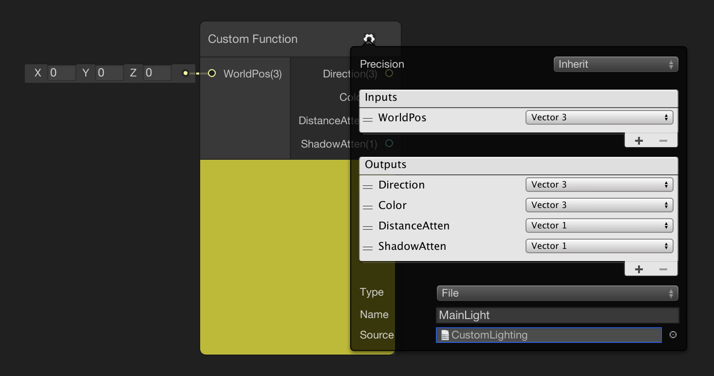
3.5 Assigning the .hlsl file
Drag the CustomLighting.hlsl file into the text asset Source slot to assign it to the custom function node:
3.6 Convert to Sub-graph
Right-click on the Custom Function node and select ‘Convert to Sub-graph’. Name the sub-graph MainLight:

3.7 Add Sub-graph Outputs
Open the new Subgraph and Connect the WorldPos input from the Custom Function node to a Position node. Also create 4 new inputs on the Output node corresponding with the outputs from the Custom Function node: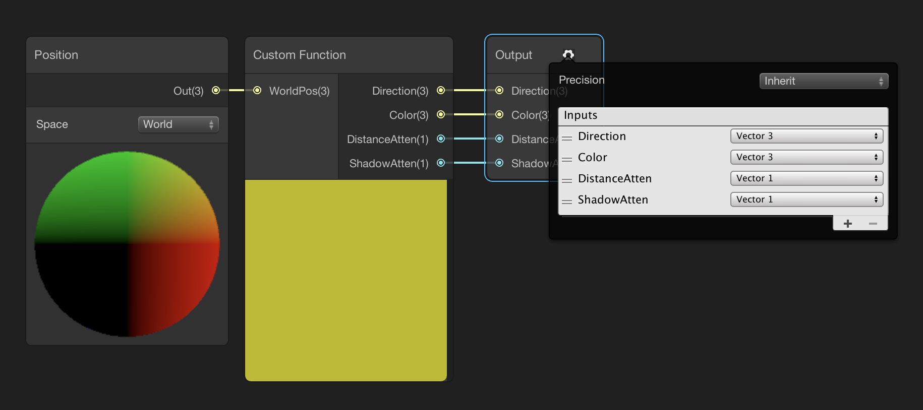
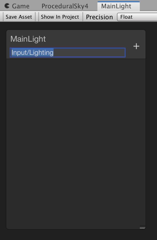
3.8 Organising the Sub-graph node
If you look at the Blackboard, you’ll see that underneath the name of the Subgraph in a darker tint grey you can specify where the subgraph is organised in the node creation menu. If you change it to Input/Lighting it will be sorted with the other Input/Lighting nodes, so it will be easy to find:
3.9 Positioning the Sun
Now that we can get the direction of the Main Light in the scene, we can use it for positioning a sun:

This graph works by getting the dot product from the view direction and the inverse direction of the main light. The size, intensity and softness of the sun can be adjusted with the radius, intensity and exponent variables. The color of the Main Light in the scene is also used to give the sun color.
3.10 Add the Sun to the Sky
The last step is to simply add the output from the Sun to the sky color with a Add node:

4.Adding a clouds layer
Building up a clouds layer has a lot of steps, but it starts simple, so for this I think it’s best if we build it up step by step, then you can decide how much information your clouds layer needs.
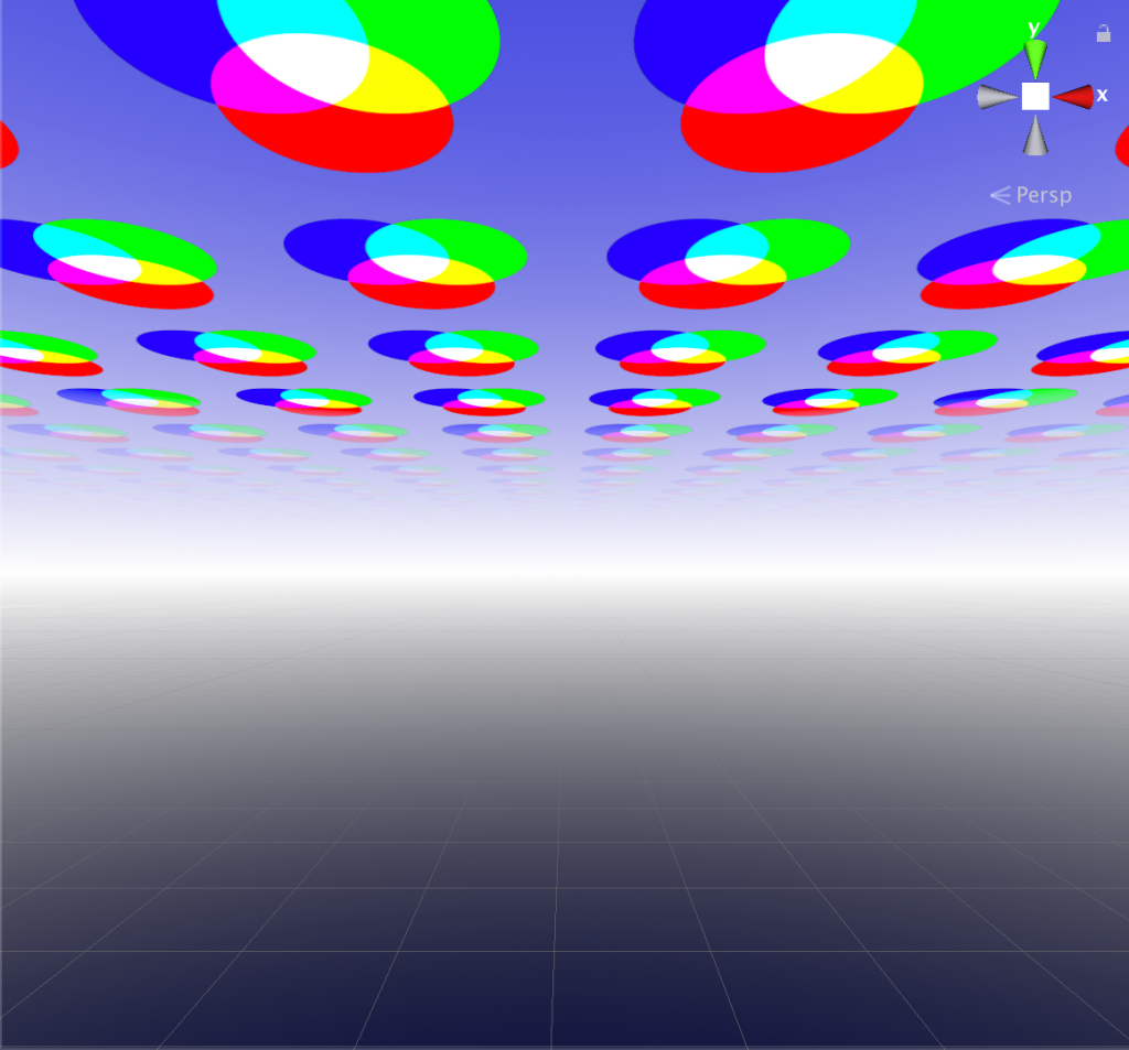
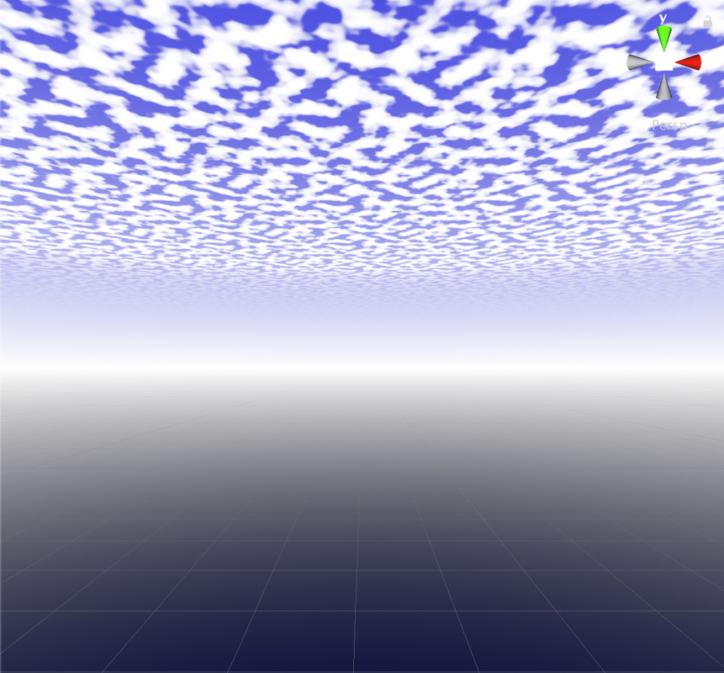
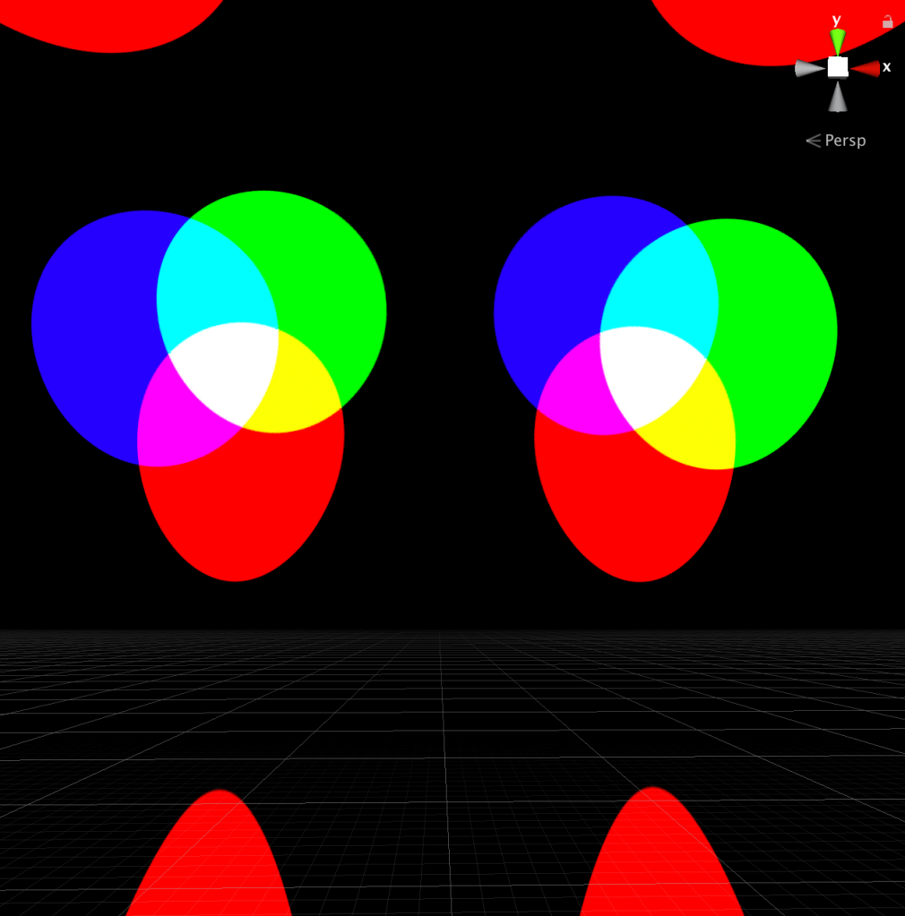
For the purpose of better showing you what’s going on this tutorial uses an RGB circles testing image created with Photoshop for most of the examples as well as a noise/clouds texture + normal map created with CatlikeCoding’s NumberFlow Unity plugin (which is also a node based application but for creating procedural textures).
You can download the textures used in this tutorial from this blogpost: https://timcoster.wordpress.com/2019/09/09/tileable-clouds-texture/
Or if you are going to use your own textures, then what probably works best is using an actual transparent .PNG file instead of a black and white one. This way you won’t get clouds with grey edges but with transparent white edges instead. Make sure to set the Alpha Source to Input Texture Aplha in the import settings and also make sure the texture has an Alpha channel, you can see if it has one in the preview window if you see a white A after RGB :


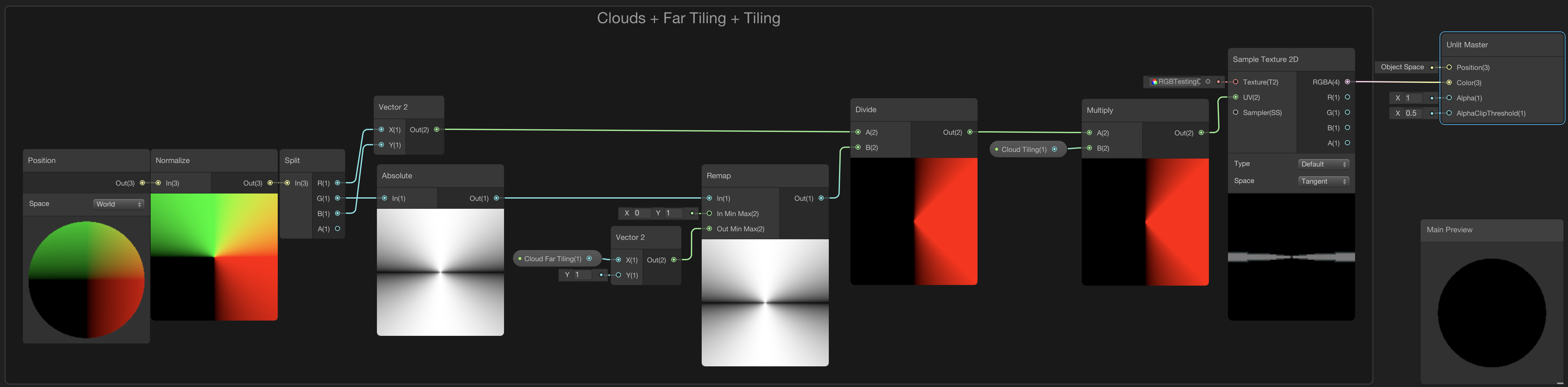
4.1 Adding a clouds layer

The node setup below generates an infinitely large flat layer for a clouds texture:

We can blend the transparent clouds texture with the sky colors and the sun, using a blend node. By using the Alpha channel from the texture for the opacity of the Blend node and setting the Blend node to overwrite, we can get a nice clean result:


4.2 Adding far tiling
By adding a property for far tiling we can make it look like the horizon is a little bit closer.
for the RGB circles example it was set to 0.1 and for the clouds to 0.25:


4.3 Adding Texture Tiling
Adding a texture tiling property gives us control over the size of the texture, here it was set to .05:


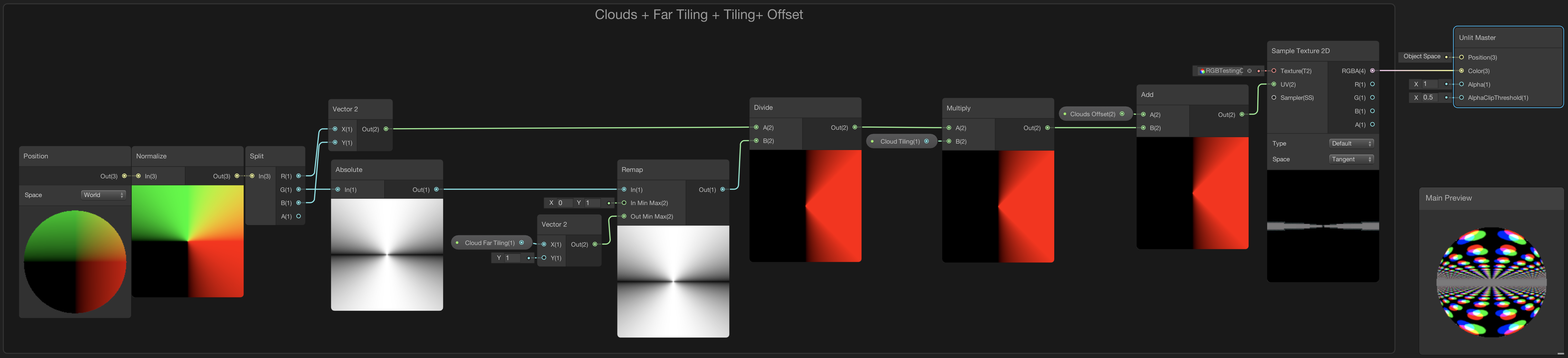
4.4 Adding Texture Offset
Adding in a Vector2 clouds texture offset property will be useful for animating the clouds later on:


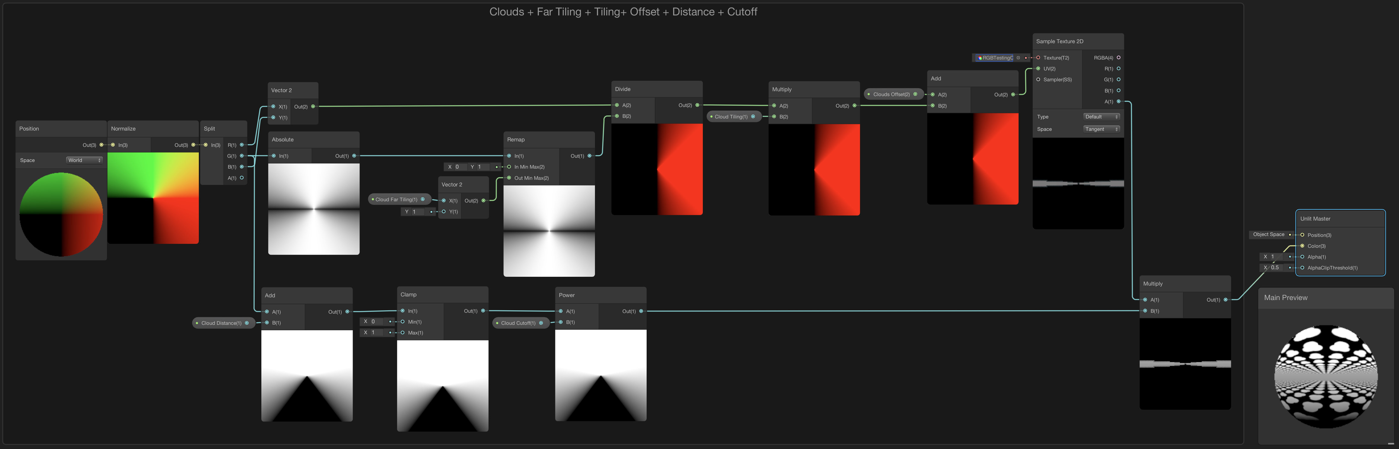
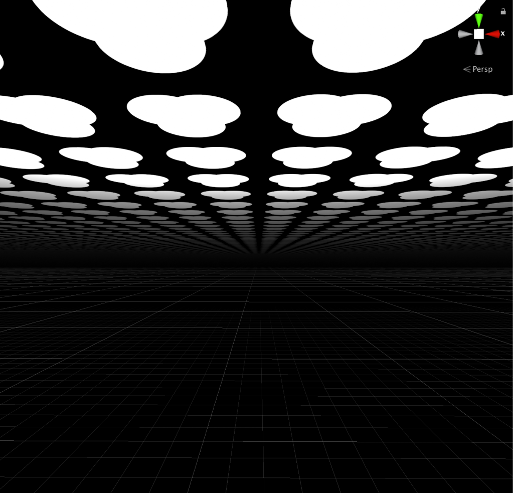
4.5 Adding Cutoff
Adding Distance and Cutoff properties to control fading out the clouds towards the horizon. For the examples below the distance was set to 0.8 and the cutoff to 25:

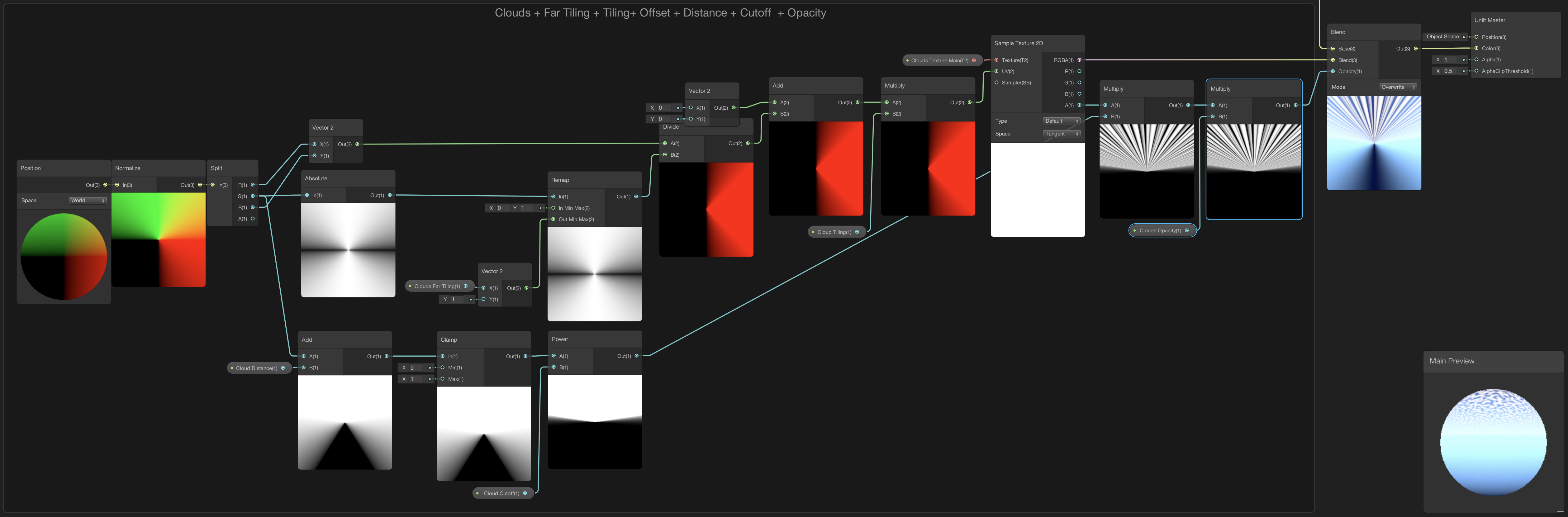
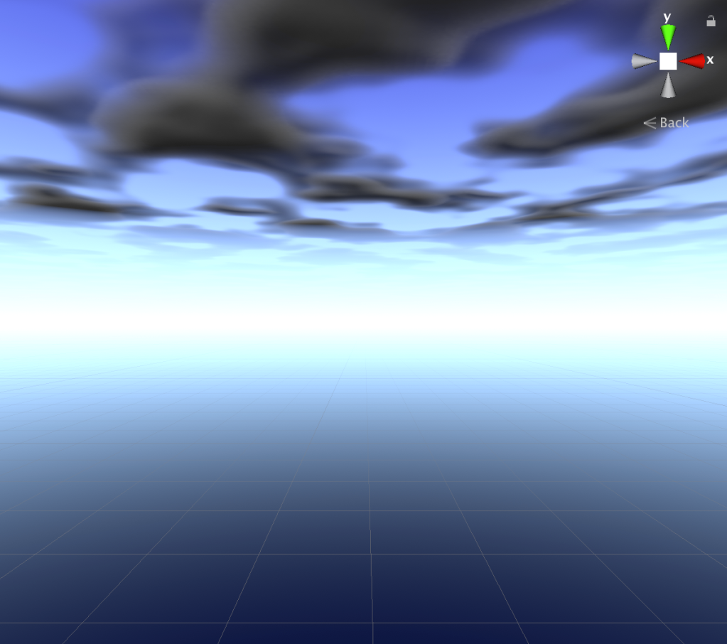
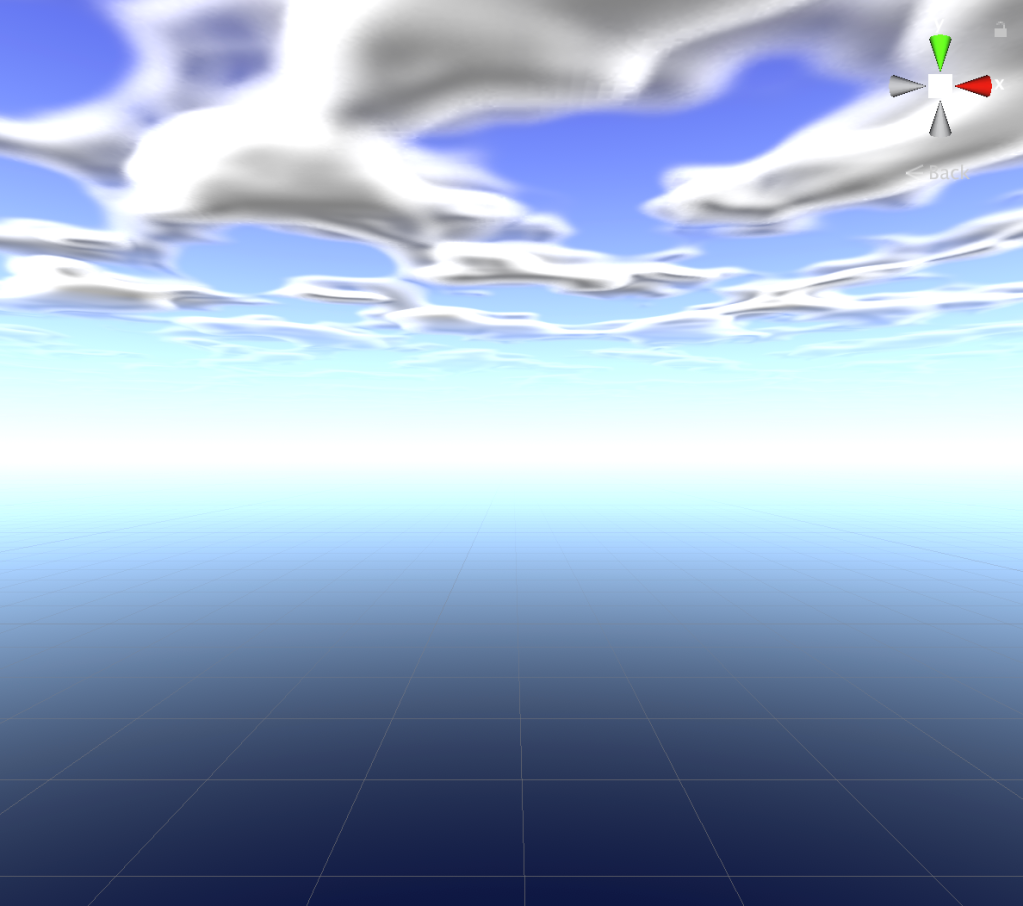
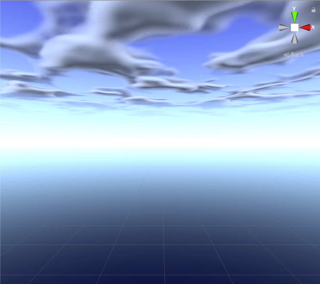
4.6 Adding Opacity
Opacity can be added by Multiplying the output of the Alpha channel of the clouds texture with a new Vector1 clouds opacity property. The example shows the opacity at 0.5:


4.7 Adding a Normal Map
Adding support for a normal map texture to suggest depth based on the direction of the light. This Makes it look like shadows are at the bottom of the clouds when the directional light shines straight down. When adding the Sample Texture node for the normal map, make sure to set the node type to Normal. Also make sure to set the clouds normal map texture property to ‘Bump’ mode on the blackboard.
The custom Main Light function node is used outside of the subgraph here because it uses the tangent position instead of the world position. You can simply copy the custom node from the Main Light subgraph.
Normal map strength was set to 0.8 for the example:


4.8 Adding Brightness
Add a new Vector1 property for clouds brightness, and a new add, subtract and multiply node.
Subtract 1 from the brightness value and then add it to the output of the blend node.
Subtracting one from the brightness will make it so that a brightness value of 1 will be normal and a value of 0 will be no brightness at all, instead of zero being the normal brightness.
Also multiply the normal map strength by the brightness property before plugging it back into the blend node, to make it dependent on the brightness value.
Left and right examples show brightness values of 0.1 and 1.5:

4.9 Adding Directional Light Color
Multiplying the texture by the Main Light color output will make the color of the clouds dependant on the color of the directional light in the scene. For the examples the light color was set to light orange and light blue:


4.10 Adding Clouds Color
Now that the hard bits for the clouds layer are done, let’s add in something a bit more easy, which is the basic clouds color. For this, make a new Color property called Clouds Color and drag it onto the graph, also make a new Blend node. Blend the Main Light color with the Clouds Color before plugging it into the multiply node at the end.
For the example below the sun color was set to light orange and the Clouds Color to light blue HDR with a high intensity:


4.11 Reorganise Layers
To make the adding of the different layers make more sense we can rearrange the graph so the order will be Sun + Sky + Clouds.
This way what is closest by will be added last:

5. Adding a Night-Sky
Now that we have a sun sky and some basic clouds we can start reaching for the stars!…(yeah, yeah..)…
But in order to see those stars better when we add them it will be handy if we can automatically transition from day-sky colors to night-sky colors using the direction of the sun for the blending between them.
We can do this by using almost the same position input that we use for the sun to Lerp from color a to b, and while we’re at it we can do the same with the sky exponent 1 and 2 properties to make the horizon look thinner at night.
So before we add the stars we’ll have to revisit the sky colors layer..
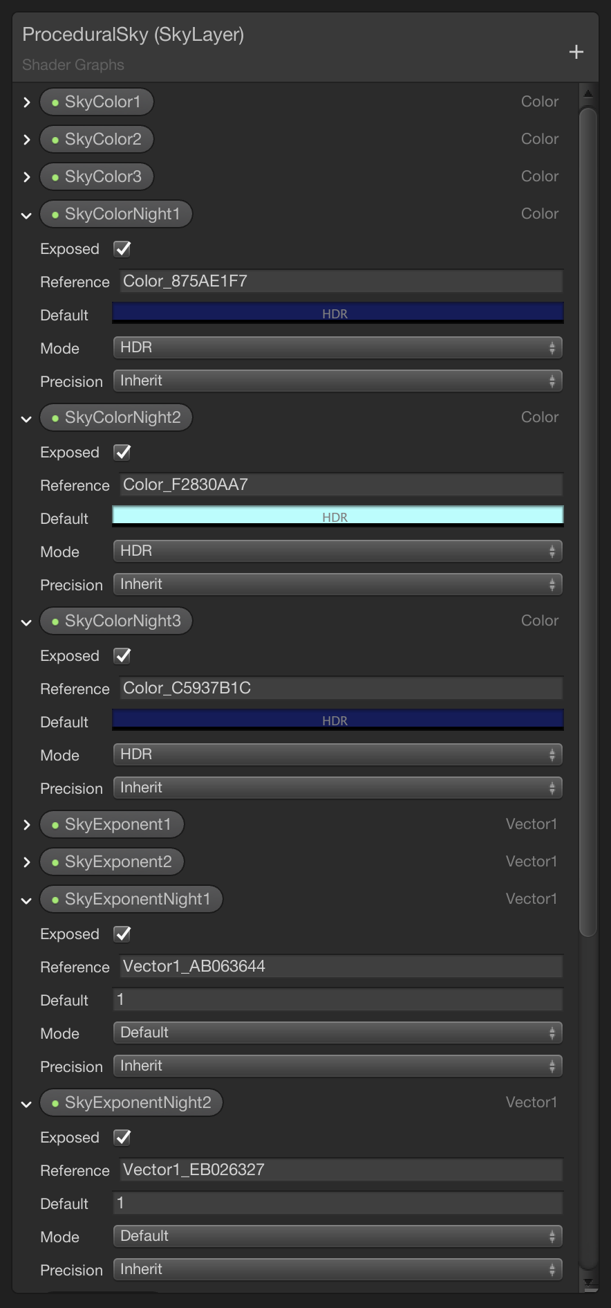
5.1 Adding night-sky properties
Add three new Color properties for the night-sky colors and add two new Vector1 properties for the night-sky exponents:
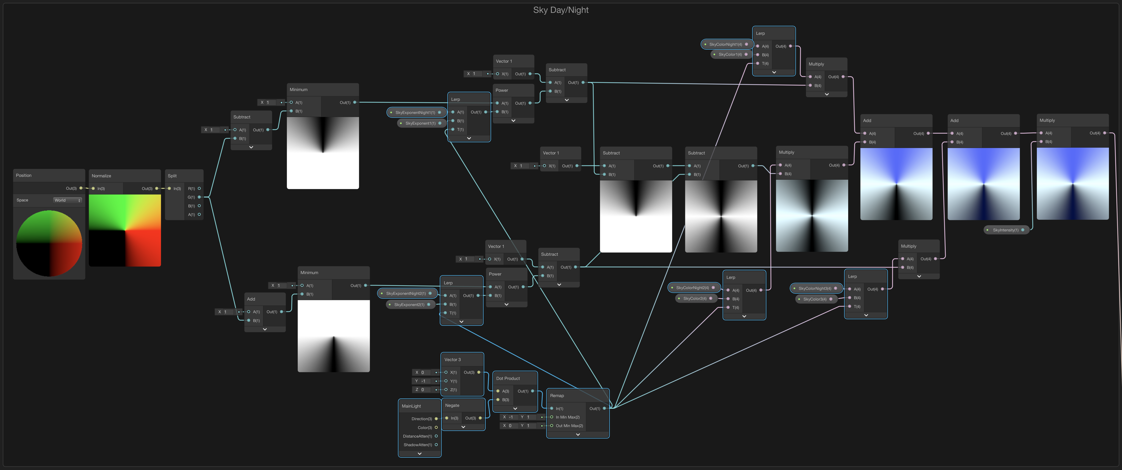
5.2 Lerping Colors
Swap the three color and two exponent property nodes with Lerp nodes and connect them in the way that you see in the diagram below.
First image is the old sky and the second is the new sky layer with all the new nodes selected so they show a blue line around them:

6. Adding Stars
Now that we can transition to dark night colors we can start adding the stars layer to the skybox. This tutorial uses a very simple black and white stars texture, but you can go as fancy as you want of course:

6.1 Sphere Mapping Space
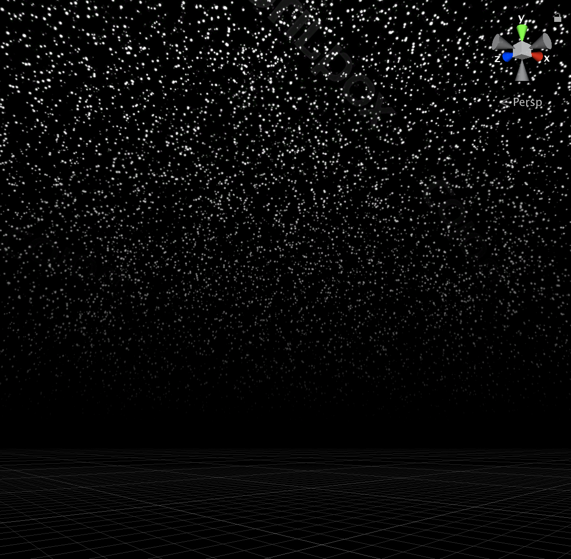
The following node setup gives us a nice spherical mapping for a stars texture. There are some weird visual artefacts from the texture not being made to wrap around a sphere but that’s not really a problem because the texture will be faded out towards the horizon:


6.3 Add Intensity
Multiply the RGB output from the stars texture by an intensity value to control how bright they shine:


6.4 Add Texture Offset
Adding a Vector2 offset value to the UV coordinates before plugging it in the texture gives us control the position of the stars texture, useful for animating later on:
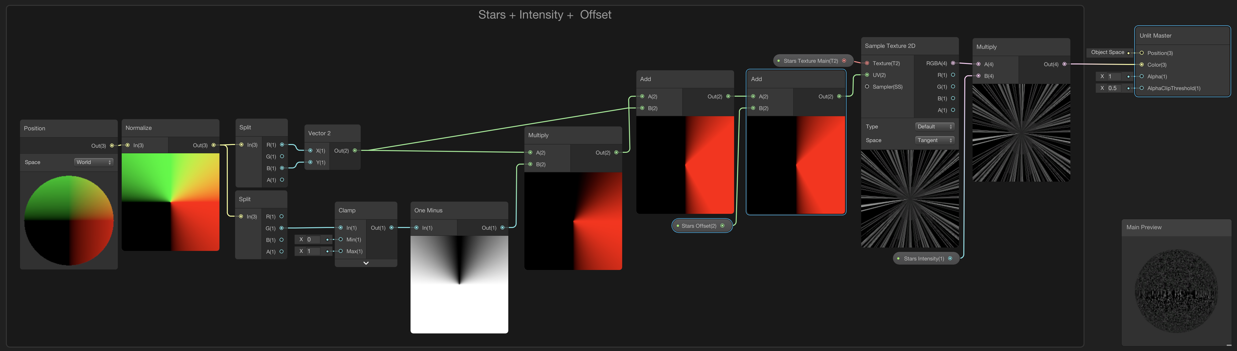
6.5 Add Horizon Fade-out
To gently fade out the stars towards the horizon we can multiply the texture again by using a power node and a fadeout property:

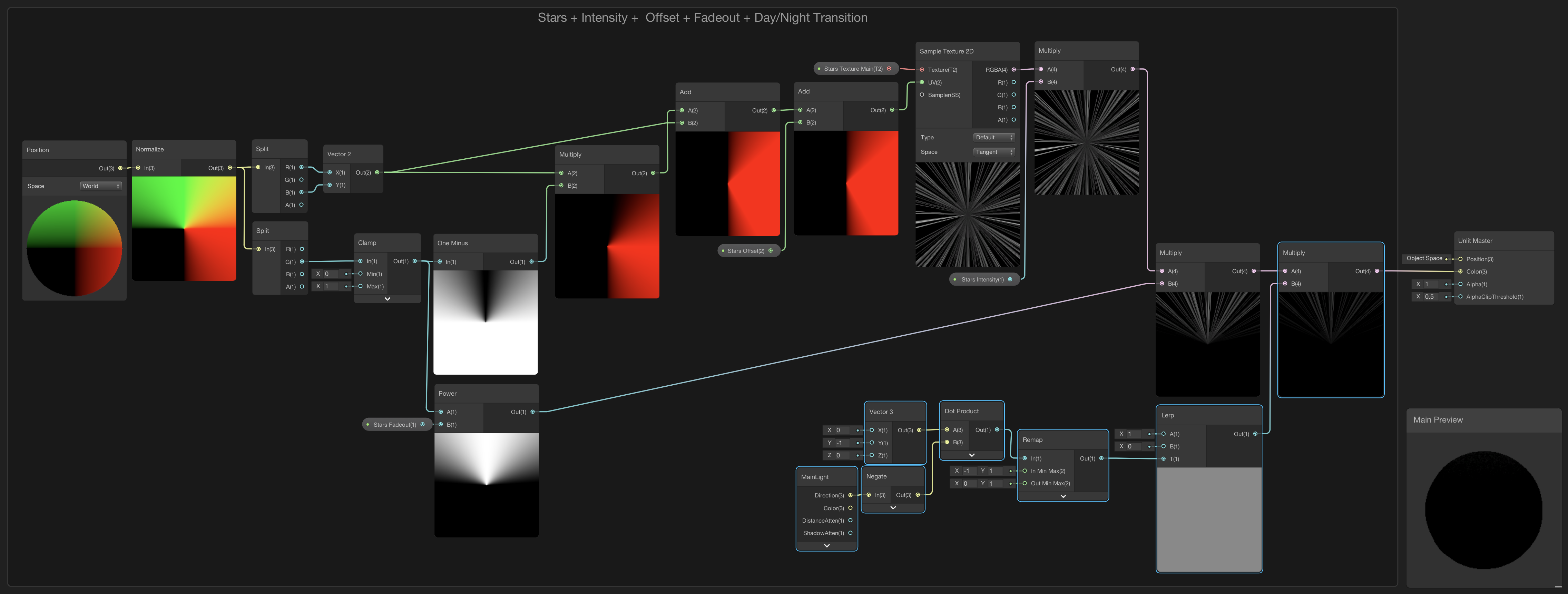
6.6 Add Day/Night Transition
Finally add a day to night transition by multiplying again by a Lerp node using the dot product of the light direction for the Lerp node’s time input. Now the stars will be completely visible when the directional light is shining straight up and completely invisible when shining straight down:
6.7 Adding the Stars Layer
Rearrange the graph so the stars come on top. They are farthest away so the stars layer is drawn first.
The complete Procedural Skybox ShaderGraph:

Adding everything up and using it on a small testing scene with a floor, exponential fog with a very low value of about 0.0006 and some post processing effects enabled it already starts to look pretty game-ee!:

7.0 Finally
Want to learn how we can access the properties of this Skybox ShaderGraph from a C# script to create a Day/Night Cycle for a game next?? Then click on the button below to go to part 2!: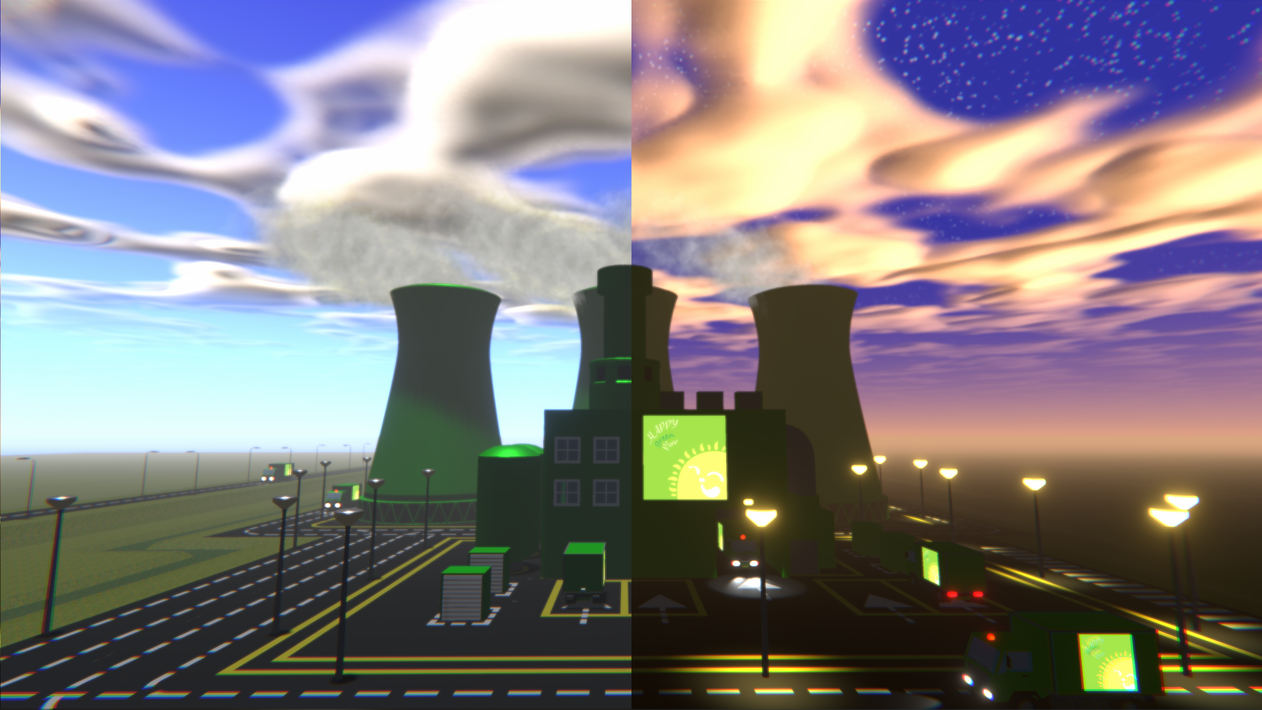

BUY ME A COFFEE
Donate $5 to buy me a coffee so I have the fuel I need to keep producing great tutorials!
$5.00
